Introduction
In the realm of surface mount technology (SMT) assembly, achieving precise solder paste application is crucial for ensuring reliable solder joints and overall product quality. Step-up stencils have emerged as a specialized tool in addressing the challenges posed by mixed component sizes and varying paste volume requirements on a single printed circuit board (PCB). These stencils allow for tailored solder paste deposition, accommodating fine-pitch components alongside larger ones. This article explores the intricacies of step-up stencil solder paste printing, focusing on critical parameters such as squeegee pressure, squeegee speed, and solder paste type. Aimed at electrical engineers, this guide provides practical insights into optimizing step-up stencil printing parameters to enhance assembly outcomes and minimize defects, aligning with industry best practices and standards for consistent, high-quality results.
What Are Step-Up Stencils and Why Do They Matter
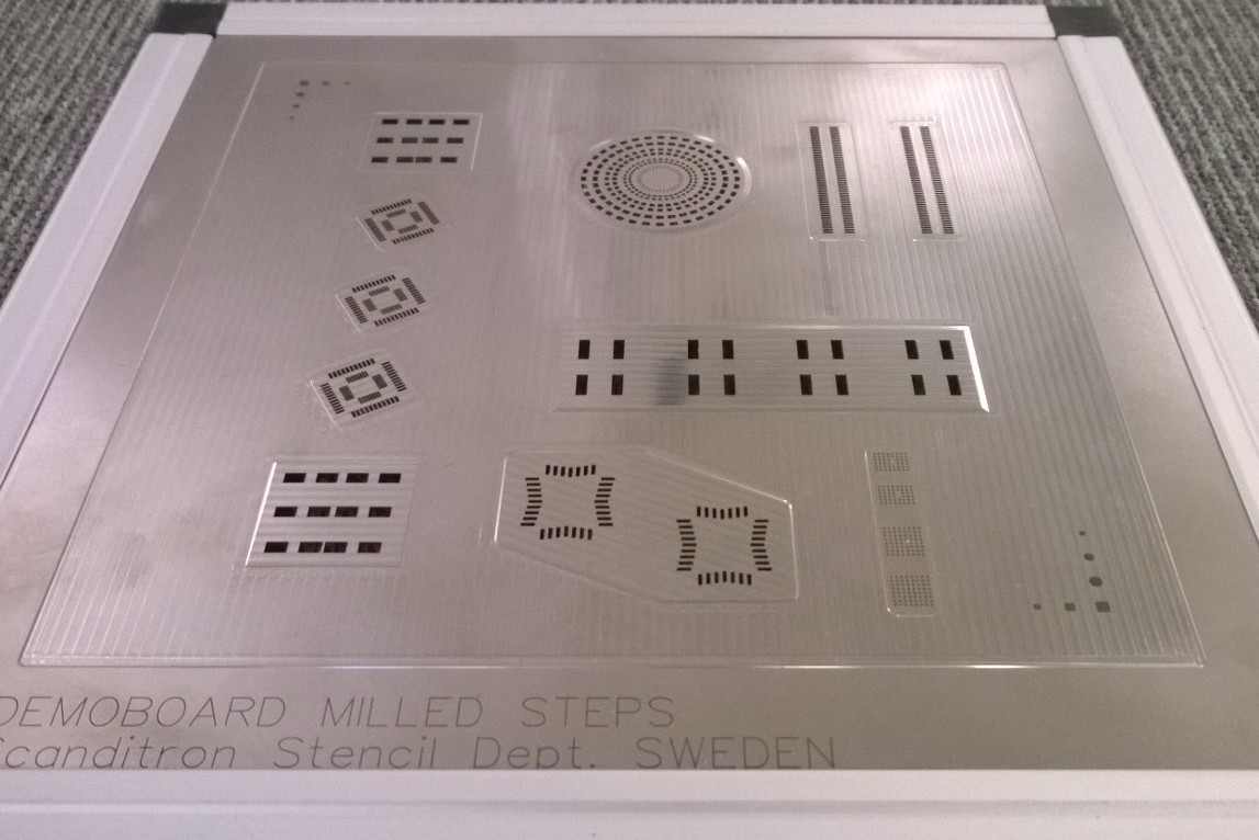
Step-up stencils are a variation of traditional SMT stencils, designed with varying thicknesses across different areas of the stencil to control solder paste volume during printing. Unlike standard stencils with uniform thickness, step-up stencils feature raised or thicker regions to deposit more paste for larger components, while thinner areas cater to fine-pitch or smaller components. This design addresses the challenge of inconsistent paste volume needs on modern PCBs, which often host a mix of component sizes.
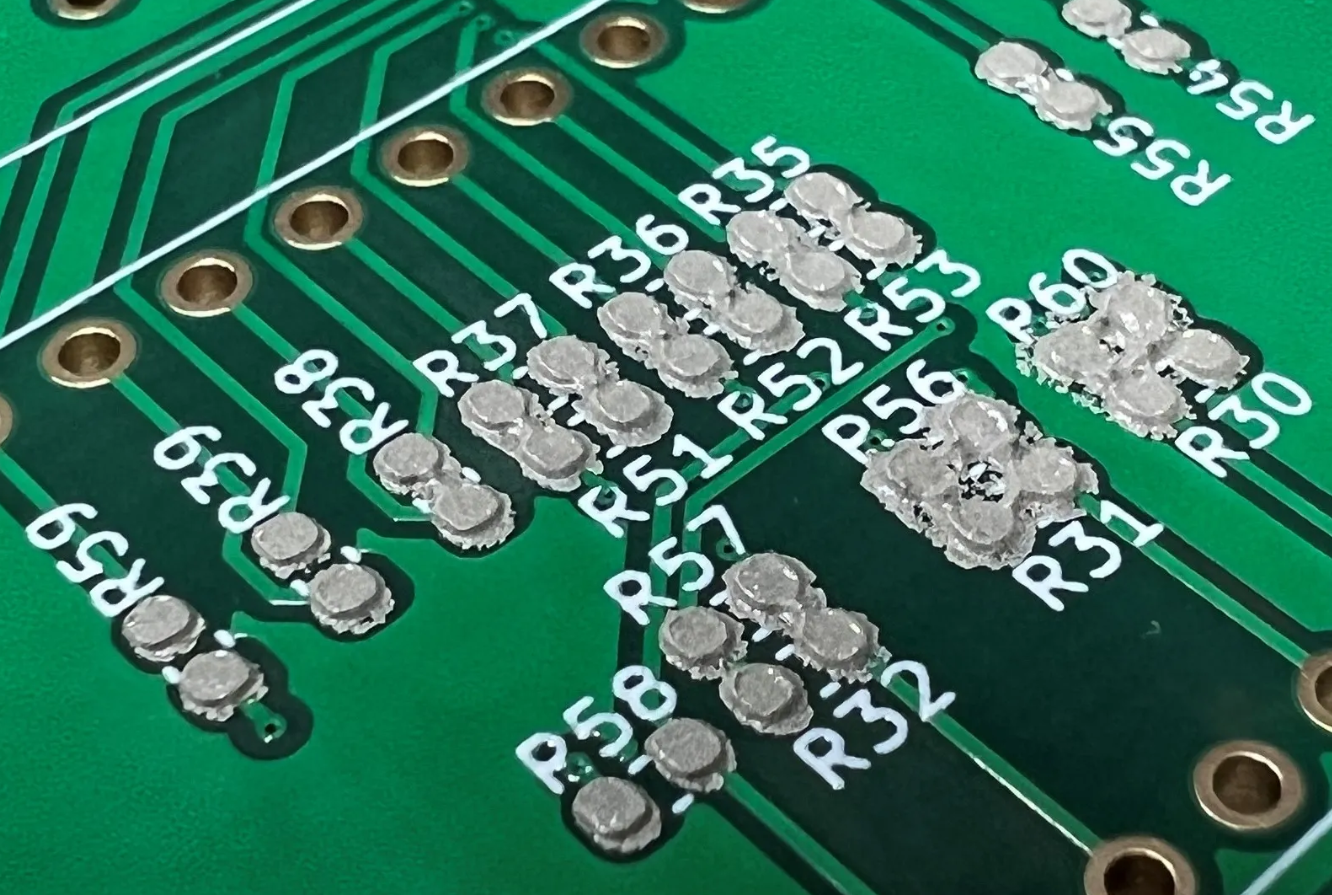
The significance of step-up stencils lies in their ability to reduce defects such as insufficient solder, bridging, or tombstoning. By customizing paste deposition, they ensure each component receives the optimal amount of solder for a reliable joint. For engineers, adopting step-up stencil solder paste printing can improve first-pass yield and lower rework costs, making it a vital technique in high-density PCBA assembly processes.
Technical Principles of Step-Up Stencil Solder Paste Printing
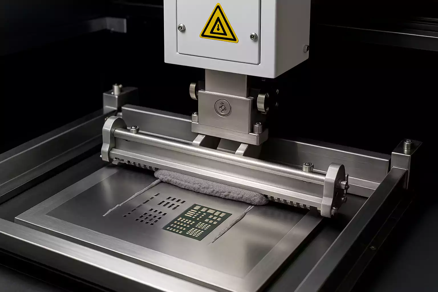
Understanding the mechanics of step-up stencil solder paste printing requires a focus on how stencil design and printing parameters interact. The primary principle is controlling paste transfer efficiency through stencil thickness variations. Thicker areas of the stencil hold and deposit more paste, ideal for components like connectors or power devices needing robust solder joints. Thinner areas limit paste volume, preventing excess deposition on fine-pitch components where bridging risks are high.
Key factors influencing the process include aperture design, stencil material, and alignment accuracy. Apertures must be precisely engineered to match pad layouts, ensuring paste is deposited only where needed. Stencil materials, often stainless steel, must withstand repeated use without deforming. Alignment between the stencil and PCB is critical to avoid misalignment defects, as even minor offsets can lead to paste misplacement.
Standards such as IPC-7525B, which provides guidelines for stencil design, emphasize the importance of aperture size and shape relative to pad dimensions. Adhering to such standards ensures that step-up stencil printing parameters are set to achieve consistent paste transfer, forming the foundation for reliable SMT assembly.
Key Parameters in Step-Up Stencil Printing
Squeegee Pressure in Step-Up Stencil Printing
Squeegee pressure plays a pivotal role in step-up stencil squeegee pressure settings. It determines how effectively solder paste is forced through the stencil apertures onto the PCB. Insufficient pressure may result in incomplete paste transfer, especially in thicker stencil areas, leading to weak solder joints. Conversely, excessive pressure can cause paste to smear or bleed under the stencil, risking defects like bridging in fine-pitch areas.
Achieving optimal pressure involves balancing force across the stencil's varying thicknesses. Engineers often start with a baseline pressure and adjust based on visual inspection of paste deposits or automated solder paste inspection (SPI) feedback. Guidelines from IPC-7525B suggest monitoring pressure to ensure clean aperture filling without damaging the stencil or PCB surface.
Squeegee Speed for Step-Up Stencils
Squeegee speed, another critical parameter in step-up stencil squeegee speed, affects paste rolling and deposition uniformity. A slower speed allows more time for paste to fill apertures, beneficial for thicker stencil regions where higher paste volume is needed. Faster speeds may be suitable for thinner areas to prevent over-deposition but risk incomplete transfer if not carefully controlled.
Finding the right speed often requires trial and error, guided by the paste's viscosity and stencil design. A common practice is to maintain a consistent speed across the stencil while monitoring paste deposit height and shape. Adjustments should align with recommendations from industry standards to ensure repeatability in step-up stencil solder paste printing.
Solder Paste Type for Step-Up Stencils
Selecting the appropriate step-up stencil solder paste type is essential for successful printing. Solder paste consists of metal alloy particles suspended in flux, and its properties, such as particle size and viscosity, directly impact printing performance. For step-up stencils, pastes with finer particles are often preferred for thin areas to ensure precise deposition through small apertures, while standard or slightly coarser pastes may suit thicker regions.
Compatibility with reflow profiles and component requirements must also be considered. Standards like IPC J-STD-005A provide criteria for solder paste selection, focusing on alloy composition and flux activity. Engineers should evaluate paste behavior under varying stencil thicknesses to prevent issues like slump or insufficient wetting during reflow.
Overall Step-Up Stencil Printing Parameters
Beyond individual factors, integrating step-up PCB SMT stencil printing parameters into a cohesive process is vital. This includes stencil thickness transitions, separation speed between stencil and PCB after printing, and environmental conditions like temperature and humidity. Maintaining a clean stencil surface prevents paste buildup, which can alter deposition volumes. Regular inspection and adjustment of parameters ensure consistency, aligning with guidelines from IPC-7525B for optimal SMT outcomes.
Practical Solutions for Optimizing Step-Up Stencil Printing
To achieve reliable results with step-up stencil solder paste printing, engineers can adopt several best practices tailored to assembly challenges. Start by collaborating with stencil designers to ensure thickness variations match component requirements. Use design software adhering to IPC-7525B guidelines to simulate paste transfer and identify potential issues before manufacturing.
During setup, calibrate squeegee pressure and speed iteratively. Begin with manufacturer-recommended settings for the solder paste type, then adjust based on SPI data to fine-tune deposits. Maintain a controlled environment to minimize variables like humidity affecting paste viscosity. Regular stencil cleaning, using methods outlined in industry standards, prevents contamination and ensures consistent aperture performance.
Post-printing inspection is critical. Employ automated SPI systems to measure paste volume and detect deviations across different stencil regions. Address any inconsistencies by tweaking step-up stencil printing parameters, focusing on pressure and speed balance. Documenting adjustments and outcomes builds a knowledge base for future projects, enhancing process repeatability.
Troubleshooting Common Issues with Step-Up Stencils
Even with optimized settings, challenges can arise during step-up stencil solder paste printing. Insufficient paste in thicker regions often stems from low squeegee pressure or high speed, preventing full aperture filling. Increase pressure slightly or reduce speed, verifying results with SPI. Bridging in fine-pitch areas may indicate excessive pressure or paste viscosity mismatch. Lower pressure or select a paste with finer particles, per IPC J-STD-005A recommendations.
Stencil wear or misalignment can also disrupt printing. Inspect stencils regularly for deformation, especially in transition zones between thicknesses. Ensure precise PCB alignment using fiducial marks and automated vision systems. If paste slump occurs post-printing, evaluate environmental conditions and paste storage, adhering to manufacturer guidelines for temperature control.
Conclusion
Step-up stencils offer a powerful solution for managing diverse solder paste requirements in modern PCB assembly. By carefully optimizing step-up stencil printing parameters, including squeegee pressure, squeegee speed, and solder paste type, engineers can achieve precise deposition and minimize assembly defects. Adhering to established standards ensures consistency and reliability in step-up stencil solder paste printing processes. With practical strategies and diligent troubleshooting, this technique enhances SMT outcomes, supporting the production of high-quality, complex electronic assemblies for demanding applications.
FAQs
Q1: How does step-up stencil squeegee pressure affect solder paste printing quality?
A1: Step-up stencil squeegee pressure directly impacts how solder paste fills stencil apertures. Too little pressure leads to incomplete deposits, especially in thicker areas, risking weak joints. Excessive pressure can cause smearing or bridging in fine-pitch zones. Adjusting pressure based on stencil design and paste type, while monitoring with inspection tools, ensures uniform application and reliable results in SMT assembly.
Q2: What is the ideal step-up stencil squeegee speed for mixed component PCBs?
A2: Finding the ideal step-up stencil squeegee speed depends on stencil thickness and paste properties. Slower speeds aid paste transfer in thicker regions, while faster speeds suit thinner areas to avoid excess. Testing different speeds and using solder paste inspection feedback helps balance deposition. Consistency across runs is key to maintaining quality for mixed component layouts.
Q3: How do I choose the right step-up stencil solder paste type for my project?
A3: Selecting a step-up stencil solder paste type involves matching particle size and viscosity to stencil design. Finer particles work for small apertures in thin areas, while standard sizes suit thicker zones. Consider alloy composition and flux activity per industry guidelines. Testing paste under actual printing conditions ensures compatibility with components and reflow requirements.
Q4: Why are step-up stencil printing parameters critical for high-density PCBs?
A4: Step-up stencil printing parameters like pressure, speed, and paste type control solder volume across varied component sizes on high-density PCBs. Proper settings prevent defects such as bridging or insufficient solder. Fine-tuning these parameters ensures each pad receives the right paste amount, supporting reliable joints and reducing rework in complex SMT assembly processes.
References
IPC-7525B — Stencil Design Guidelines. IPC, 2011.
IPC J-STD-005A — Requirements for Soldering Pastes. IPC, 2012.


