Introduction
As an electronic hobbyist, you have likely spent hours designing and assembling your first printed circuit board assembly, or PCBA. A PCBA takes a bare PCB and populates it with electronic components, creating a functional circuit ready for your project. However, even the best solder joints can fail under real-world stresses like heat, vibration, or humidity. This PCBA testing guide introduces basic PCBA reliability testing in a step-by-step format tailored for beginners. Reliability testing verifies that your assembly withstands everyday use without unexpected breakdowns. By following these beginner PCB test methods, you can build confidence in your projects and troubleshoot issues early.
Reliability matters because hobby projects often operate in uncontrolled environments, such as drones exposed to wind or sensors in garages with temperature swings. Skipping tests might lead to frustrating failures after deployment. This guide focuses on accessible tools like a multimeter and magnifying glass, avoiding expensive lab equipment. You will learn to spot common defects and simulate stresses safely. Basic PCBA reliability ensures your electronic components guide leads to durable results. Start with simple checks and progress to environmental simulations for comprehensive validation.
What Is PCBA Reliability Testing?
PCBA reliability testing evaluates how well an assembled board performs over time under various stresses. It goes beyond initial functionality to check for weaknesses in solder joints, component placement, and material integrity. Electrical tests confirm connections, while environmental tests mimic operational conditions like temperature changes. For hobbyists, this means using everyday tools to replicate field stresses without specialized chambers. Standards like IPC-A-610 provide criteria for visual acceptability, helping you judge assembly quality objectively.
Reliability testing identifies failure modes before they occur in your project. Poor solder joints might crack from vibration, or components could lift from thermal expansion mismatch. Beginners often overlook these until the board fails during use. A solid PCBA testing guide incorporates both quick checks and longer stress tests. This approach builds basic PCBA reliability from the ground up.
Why PCBA Reliability Testing Matters for Electronic Hobbyists
Failures in hobby projects waste time, components, and enthusiasm. A drone PCBA that shorts mid-flight or a home automation board that overheats can derail your efforts. Reliability testing catches these issues early, saving resources and boosting success rates. It also teaches you about electronic components guide principles, like how capacitors handle heat or resistors withstand vibration. For beginners, consistent testing turns trial-and-error into predictable outcomes.
In uncontrolled hobby environments, boards face coffee spills, bumpy rides, or attic heat. Professional standards emphasize this, but hobbyists adapt them practically. Testing aligns your work with industry practices, preparing you for more complex builds. Ultimately, basic PCBA reliability extends project lifespan and encourages experimentation.
Key Technical Principles Behind PCBA Reliability
Solder joints form the backbone of PCBA reliability, acting as mechanical and electrical bridges between components and the board. Thermal expansion differences between metals and substrates create stress during temperature swings, potentially causing cracks. Vibration induces fatigue in leads and joints, while humidity promotes corrosion on exposed pads. Understanding these mechanisms helps hobbyists prioritize tests. Moisture trapped in components can lead to delamination during reflow, as outlined in JEDEC J-STD-020 guidelines.
Component selection influences reliability; through-hole parts offer mechanical strength, while surface-mount demands precise soldering. Board warpage from uneven heating affects joint alignment over time. Electrical principles like resistance changes signal early degradation. Beginners benefit from grasping these basics to interpret test results accurately.
Step-by-Step Guide to Beginner PCB Tests
Step 1: Preparation and Documentation
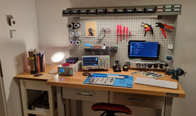
Begin your PCBA testing guide by organizing your workspace to prevent ESD damage, using a grounded mat and wrist strap if available. Gather tools: digital multimeter, 10x magnifier or loupe, fine probe set, and optional heat gun or fan for thermal simulation. Document your board with photos of both sides before testing. Note component values and expected voltages from your schematic. Clean the board gently with isopropyl alcohol to remove flux residues that could skew readings. This setup ensures repeatable, troubleshooting-focused results.
Step 2: Visual Inspection
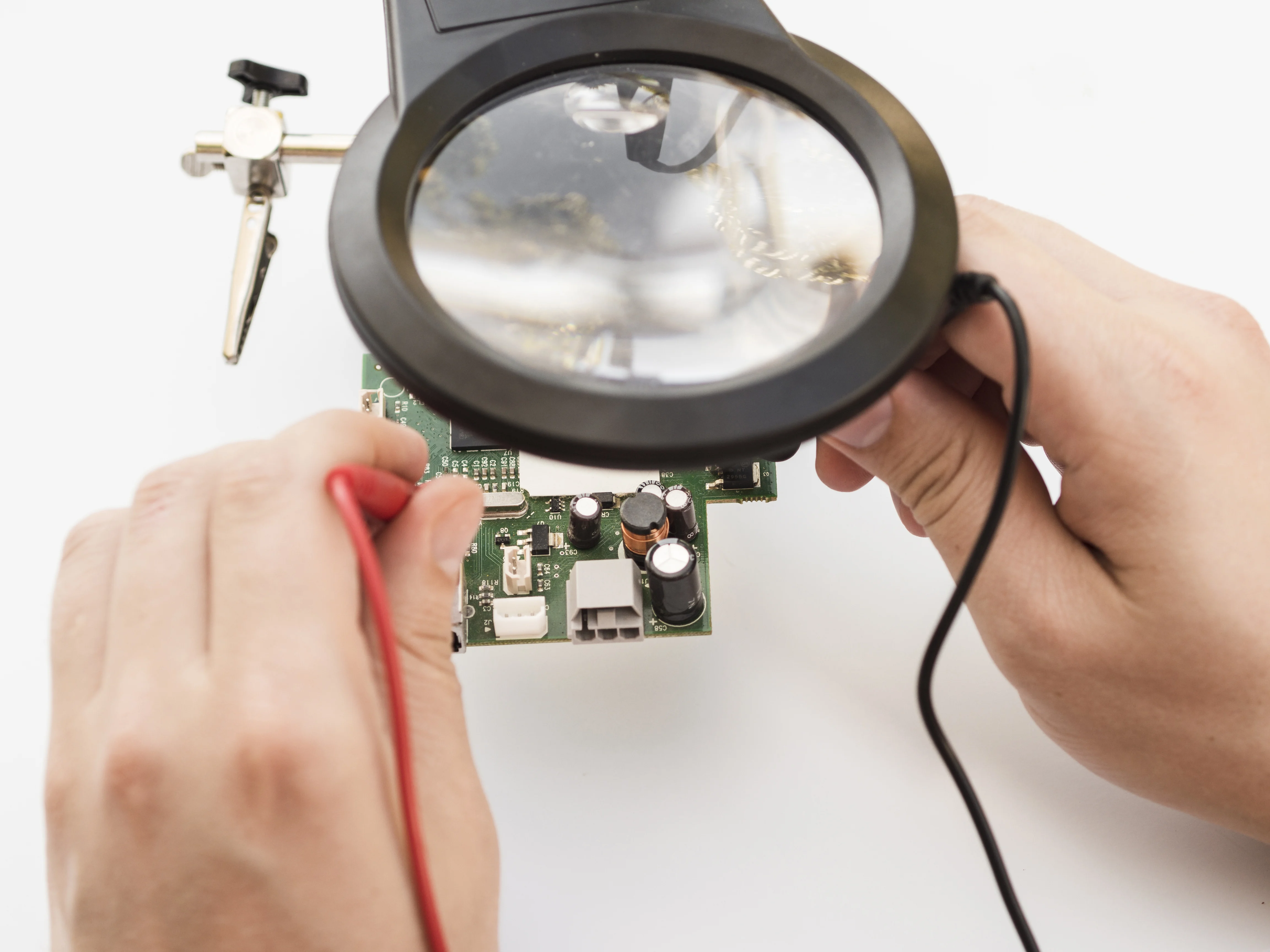
Perform a thorough visual check under good lighting, scanning for solder bridges, cold joints, or tombstoned components. IPC-A-610 class 2 criteria suit hobbyists, accepting minor cosmetic issues but rejecting voids larger than half the pad. Inspect pad wetting, where solder should cover 75% of the pad surface for reliability. Check for lifted traces or excessive solder balls that could cause shorts. Rotate the board to catch shadows revealing defects. This beginner PCB test step catches 80% of assembly flaws without tools.
Step 3: Electrical Continuity and Insulation Tests
Set your multimeter to continuity mode and probe each net against your schematic, beeping for good connections. Test for opens by checking resistance below 10 ohms on traces and joints. Switch to high-resistance mode for insulation, ensuring over 1 megaohm between adjacent nets to prevent leakage. Probe power and ground planes separately. Repeat after flexing the board lightly to simulate handling stress. These basic tests verify electronic components guide integrity post-assembly.
Step 4: Functional and Power-Up Testing
Apply power at rated voltage, monitoring current draw with the multimeter in series. Verify outputs like LED glow or sensor readings match expectations. Use a logic probe for digital signals if applicable. Cycle power 10-20 times to check for startup issues. Watch for overheating components signaling shorts or poor grounding. Log voltages at key nodes; deviations indicate joint weakness. This step confirms real-world operation in your PCBA testing guide.
Step 5: Basic Environmental Stress Tests
Simulate thermal stress by placing the powered board near a heat source like a 60-80°C oven for 30 minutes, then cool to room temperature. Monitor for intermittent failures during cycles. For vibration, secure the board and shake gently for 5 minutes while powered, listening for glitches. Humidity test involves a sealed bag with damp sponge overnight, checking corrosion after. Avoid extremes to prevent damage. These mimic field conditions for basic PCBA reliability.
Step 6: Analysis and Iteration
Review all data against baselines, noting any failures. Cross-reference with J-STD-001 soldering requirements for joint quality. Rework suspect areas and retest. Track failure modes in a log for future designs. If vibration caused opens, reinforce with epoxy. This troubleshooting loop refines your skills.
Best Practices and Common Troubleshooting Pitfalls
Always work in a static-safe area to avoid zapping sensitive chips. Use fresh flux and solder for better joints, cleaning thoroughly post-assembly. Calibrate your multimeter periodically for accurate readings. Common pitfalls include rushing visual checks, missing microcracks visible only under magnification. Overheating during thermal tests warps boards; monitor closely. For troubleshooting, isolate sections by removing components systematically.
Document failures with photos for patterns, like repeated shorts from flux residue. Select components rated for your operating range. Space parts to reduce thermal crowding. These practices elevate basic PCBA reliability.
Conclusion
This PCBA testing guide equips electronic hobbyists with practical steps for reliable boards. From visual checks to stress simulations, each phase builds confidence. Referencing standards like IPC-A-610 ensures professional alignment without complexity. Troubleshoot proactively to extend project life. Experiment safely, iterating on lessons learned. Your next build will perform better, turning hobby into mastery.
FAQs
Q1: What is a basic PCBA reliability test for beginners?
A1: A beginner PCB test starts with visual inspection for solder defects, followed by multimeter continuity checks and power-up functional verification. Add simple thermal and vibration stresses using household tools. This PCBA testing guide catches most issues early, aligning with IPC-A-610 criteria for hobby assemblies. Expect 30-60 minutes per board.
Q2: How does electronic components guide impact PCBA reliability?
A2: Component ratings for temperature and voltage directly affect basic PCBA reliability. Undersized parts fail under stress, so match specs to your application. Test interactions like capacitor ESR changes post-heat. Troubleshooting focuses on replacements during failures.
Q3: Why perform environmental tests in a PCBA testing guide?
A3: Environmental tests simulate real stresses like heat or shakes, revealing weak joints before deployment. Hobbyists use ovens or manual flexing for accessible validation. Per JEDEC guidelines, this prevents field failures in variable conditions.
Q4: What are common pitfalls in beginner PCB tests?
A4: Rushing visuals misses bridges; poor cleaning causes false shorts. Over-stress damages boards irreparably. Always document and iterate, following J-STD-001 for soldering basics.
References
IPC-A-610H — Acceptability of Electronic Assemblies. IPC, 2020
J-STD-001GS — Requirements for Soldered Electrical and Electronic Assemblies. IPC/JEDEC, 2020
JEDEC J-STD-020E — Moisture/Reflow Sensitivity Classification of Nonhermetic Surface Mount Devices. JEDEC, 2014
IPC-9701 — Performance Test Methods and Qualification Requirements for Surface Mount Solder Attachments. IPC, 2019


