Introduction
Power electronics printed circuit board assemblies, or PCBAs, form the backbone of systems operating under extreme conditions, such as electric vehicle inverters, renewable energy converters, and industrial motor drives. These assemblies manage high voltages, currents, and switching frequencies, which generate significant thermal, electrical, and mechanical stresses. Reliability in these high-stress applications directly impacts system performance, safety, and longevity, as failures can lead to catastrophic downtime or hazards. Engineers must address challenges like heat dissipation, component durability, and assembly integrity to meet demanding operational requirements. This article explores critical factors in PCBA power electronics thermal management, component selection, testing, and adherence to reliability standards. By focusing on proven engineering principles, designers can enhance robustness and extend service life in harsh environments.
Understanding Power Electronics PCBA and Its Critical Role
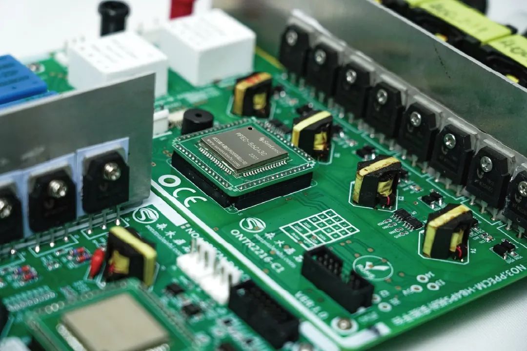
Power electronics PCBA refers to the fully assembled printed circuit boards populated with power semiconductors, capacitors, inductors, and control components tailored for high-power applications. Unlike standard consumer electronics, these assemblies handle kilowatts of power with rapid switching, often exceeding 100 kHz, which amplifies stress factors. Thermal runaway, voltage transients, and vibration from machinery pose constant threats to solder joints, traces, and dielectrics. In industries like aerospace and automotive, where downtime costs millions, PCBA reliability becomes paramount. Engineers prioritize designs that withstand cycles of power-on and environmental exposure without degradation. The integration of advanced materials and processes distinguishes reliable power electronics PCBA from conventional assemblies.
High-stress applications demand PCBAs that maintain functionality across wide temperature swings, from -40°C to over 150°C junction temperatures. Power density continues to rise with silicon carbide and gallium nitride devices, pushing thermal limits further. Poor reliability manifests as delamination, cracking, or intermittent failures, compromising entire systems. Thus, a holistic approach encompassing design, fabrication, assembly, and validation ensures these PCBAs deliver consistent performance.
Principles of PCBA Power Electronics Thermal Management
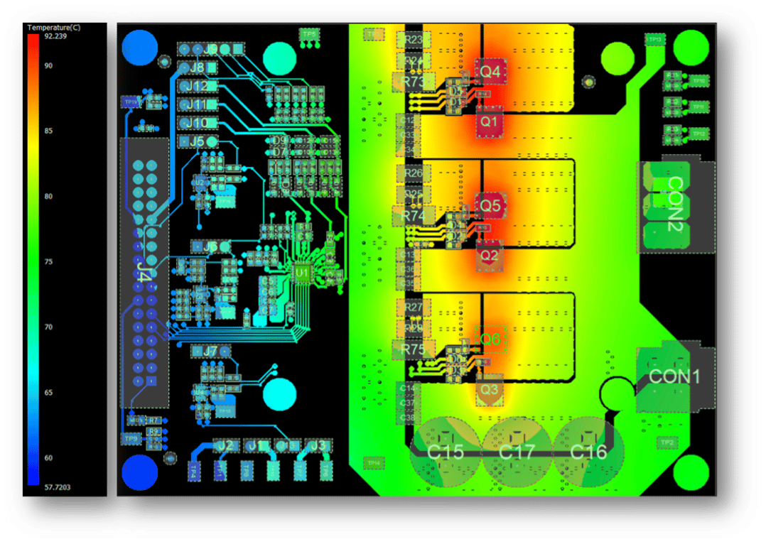
Effective PCBA power electronics thermal management begins with understanding heat generation mechanisms in power devices. Switching losses in transistors and diodes, along with conduction losses, produce localized hotspots that propagate through the board. Conduction paths via copper planes, thermal vias arrays, and embedded heat spreaders conduct heat away from critical junctions. Convection and radiation further dissipate energy, but in enclosed systems, forced air or liquid cooling becomes essential. Material selection, such as high thermal conductivity laminates, minimizes spreading resistance and gradient-induced failures.
Thermal vias, filled or plated-through, bridge layers to equalize temperatures, but their design must account for solder wicking during reflow. Multilayer stacks with dedicated power and ground planes act as heat sinks, reducing via reliance. Engineers model junction-to-ambient resistance using finite element analysis to predict hotspots. IPC-2221 provides foundational guidelines for thermal design parameters, including trace spacing and layer stacking to optimize dissipation. Overlooking these principles leads to electromigration in traces or voiding in solder joints under thermal cycling.
Advanced strategies include metal-core substrates for direct heat extraction and embedded coin technologies for die-level cooling. Surface finishes like ENIG prevent oxidation while supporting heat transfer. Validation through infrared thermography reveals real-world performance discrepancies from simulations. By balancing electrical efficiency with thermal paths, PCBA power electronics thermal management extends mean time between failures significantly.
Strategic PCBA Power Electronics Component Selection
Component selection in PCBA power electronics dictates overall reliability under stress. Power semiconductors like IGBTs and MOSFETs must exhibit low on-resistance and high avalanche ratings to handle transients. Capacitors require high ripple current capability and low ESR to filter switching noise without overheating. Inductors demand core materials resistant to saturation at peak currents. Derating factors, typically 50-80% of rated values, account for aging and overstress, ensuring margin in high-stress scenarios.
Qualification focuses on datasheets specifying maximum junction temperatures, thermal cycling endurance, and safe operating areas. Surface-mount devices with bottom-side cooling tabs enhance dissipation compared to through-hole. Packaging types, such as TO-247 for discretes or QFN for integrated modules, influence parasitic inductance and thermal impedance. JEDEC standards classify moisture sensitivity levels, preventing popcorn effects during assembly. Selecting components with matching coefficients of thermal expansion avoids solder joint fatigue.
Reliability data from manufacturer curves guides choices, prioritizing those with proven field performance in similar applications. Gate drivers and passives must tolerate voltage spikes from fast di/dt. Inventory management ensures lot traceability for failure analysis. Thoughtful PCBA power electronics component selection mitigates risks from diverse stress vectors.
Rigorous PCBA Power Electronics Testing Protocols
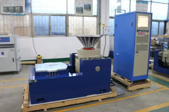
Testing validates PCBA power electronics against anticipated stresses through accelerated life methods. Thermal cycling per IEC 60068-2-14 exposes assemblies to -55°C to 125°C ramps, revealing CTE mismatch cracks. Power cycling simulates operational duty, monitoring resistance rise in switches and joints. Vibration testing per IEC 60068-2-6 assesses mechanical integrity under sinusoidal or random profiles up to 50g.
Electrical testing includes high-potential isolation, partial discharge detection, and surge withstand per application profiles. Functional hot/cold testing verifies performance shifts. Highly accelerated life testing (HALT) uncovers weak links via stepwise stressors. In-circuit and flying probe tests catch assembly defects pre-stress.
Post-test cross-sections analyze microcracks via dye penetrant or scanning electron microscopy. Data logging tracks degradation metrics like leakage current or forward voltage drop. Iterative testing refines designs. Comprehensive PCBA power electronics testing bridges simulation to field reality.
Adhering to PCBA Power Electronics Reliability Standards
PCBA power electronics reliability standards provide benchmarks for qualification and process control. IPC-9592B defines classes for power conversion devices, specifying design margins, test sequences, and MTBF targets tailored to mission profiles. Compliance ensures assemblies meet Level 2 or 3 requirements for telecom or harsh environments. J-STD-001 outlines soldering criteria for high-reliability joints, emphasizing void limits and fillet formation under power reflow.
Standards mandate documentation of process controls, from stencil aperture to nitrogen reflow atmospheres. Audits verify calibration and operator certification. Failure mode effects analysis integrates standard requirements into design. Non-conformance triggers root cause via 8D methodology.
Global harmonization via IPC, JEDEC, and IEC facilitates supply chain consistency. Regular recertification adapts to evolving technologies like wide-bandgap devices. Strict adherence elevates PCBA power electronics reliability standards from guidelines to imperatives.
Best Practices for Implementation
Layout optimization separates power and signal paths to minimize EMI coupling. Wide traces and polygons handle current without excessive voltage drop. Fiducials and panelization aid precision assembly. Solder paste inspection prevents bridging on fine-pitch QFNs.
Reflow profiling matches component tolerances, with peak temperatures controlled to avoid intermetallic growth. X-ray inspection detects voids in BGAs. Conformal coatings protect against humidity ingress. Supply chain qualification ensures component authenticity.
Field telemetry monitors in-service performance, feeding back into designs. Collaborative DFM reviews preempt issues. These practices holistically fortify reliability.
Conclusion
Ensuring reliability in power electronics PCBA demands integrated attention to thermal management, component selection, testing, and standards compliance. Engineers who master these elements deliver assemblies resilient to high-stress rigors. From thermal vias to vibration quals, each decision compounds robustness. Adopting best practices and standards like IPC-9592B positions designs for success in demanding sectors. Ultimately, reliable PCBA power electronics safeguards innovation and operational continuity.
FAQs
Q1: What are key strategies in PCBA power electronics thermal management?
A1: PCBA power electronics thermal management relies on thermal vias, thick copper layers, and high-conductivity substrates to spread heat from hotspots. Modeling tools predict junction temperatures, while derating ensures margins. Infrared validation confirms dissipation efficacy. Compliance with IPC-2221 aids trace sizing for current loads. These steps prevent thermal runaway and extend component life.
Q2: How does component selection impact PCBA power electronics reliability?
A2: PCBA power electronics component selection emphasizes ratings for voltage, current, and temperature exceeding operational peaks. Derating by 50% minimum accommodates stresses. JEDEC moisture classifications prevent reflow damage. Matching thermal expansion coefficients reduces fatigue. Proven datasheets and field data guide choices for long-term durability.
Q3: What testing methods ensure PCBA power electronics reliability?
A3: PCBA power electronics testing includes thermal cycling, power cycling, and vibration per IEC 60068 to simulate stresses. HALT identifies weaknesses early. Electrical surge and isolation tests verify integrity. Post-test analysis via microscopy detects microcracks. Comprehensive protocols validate against failure modes.
Q4: Why follow PCBA power electronics reliability standards?
A4: PCBA power electronics reliability standards like IPC-9592B define qualification classes, test margins, and process controls for consistent performance. They mitigate risks in high-stress apps. J-STD-001 ensures solder joint quality. Adherence streamlines certification and supply chains, boosting MTBF.
References
IPC-9592B — Requirements for Power Conversion Devices for the Computer and Telecommunications Industries. IPC, 2014
IPC-2221B — Generic Standard on Printed Board Design. IPC, 2003
J-STD-001H — Requirements for Soldered Electrical and Electronic Assemblies. IPC, 2018
IEC 60068-2 — Environmental Testing. IEC, ongoing series


