Introduction
In modern electronics manufacturing, fine-pitch PCBs demand exceptional precision during solder paste application to ensure reliable assembly yields. Stencil printers play a pivotal role in depositing uniform solder paste volumes onto tiny pads, especially for components with pitches as small as 0.4mm. As board densities increase, even minor variations in print quality can lead to widespread defects downstream in the surface mount technology process. Engineers must master stencil printer operations, from setup to parameter tuning, to achieve consistent results. This article explores the intricacies of fine pitch stencil design, common solder paste printing defects, and practical strategies for using a stencil printer for 0.4mm pitch components effectively. By focusing on proven engineering approaches, you can optimize your SMT lines for high-reliability production.

Understanding Stencil Printing and Its Critical Role in Fine-Pitch Assembly
Stencil printing involves forcing solder paste through precisely etched apertures in a thin metal foil onto PCB pads using a squeegee blade. This process sets the foundation for component placement and reflow soldering, directly influencing joint integrity. For fine-pitch devices like QFNs or BGAs at 0.4mm pitch, the margin for error shrinks dramatically, requiring sub-25 micron alignment tolerances. Poor print quality amplifies risks in subsequent steps, such as tombstoning or open joints. Engineers prioritize stencil printing because it accounts for up to 60 percent of SMT defects if not controlled properly. Mastering this step ensures scalability for high-volume production while minimizing rework costs.
The relevance intensifies with shrinking component sizes driven by 5G, automotive, and consumer electronics demands. Traditional printing parameters that work for coarser pitches fail here, necessitating specialized fine pitch stencil design. Printer vision systems and automated cleaning cycles become essential tools in the arsenal. Ultimately, precise solder paste application bridges design intent with manufacturable reality, upholding assembly standards like IPC-610 for acceptability criteria.
Core Technical Principles of Solder Paste Printing
Solder paste, a suspension of flux and metal powders, exhibits thixotropic behavior, flowing under shear from the squeegee but holding shape post-print. The printer mechanism aligns the stencil to the PCB, applies controlled pressure via polyurethane or metal squeegees, and lifts the stencil with snap-off distance to cleanly release paste. Key variables include print speed, typically 20 to 80 mm per second, and downward force around 2 to 5 kg per blade length. For fine features, paste transfer efficiency hinges on the aperture's area ratio, defined as open area divided by wetted wall perimeter. Low ratios below 0.6 lead to incomplete fills, while high ratios risk bridging.
Stencil material, often electroformed nickel or laser-cut stainless steel, affects release properties. Etch factors determine sidewall quality, with trapezoidal profiles preferred for fine-pitch apertures to ease paste release. Board and stencil flatness interact dynamically; warpage over 0.075 mm per side can distort prints. Environmental controls, like 23 to 25 degrees Celsius and 40 to 60 percent relative humidity, stabilize paste viscosity. These principles form the engineering backbone for troubleshooting inconsistencies in production.
Fine Pitch Stencil Design Essentials
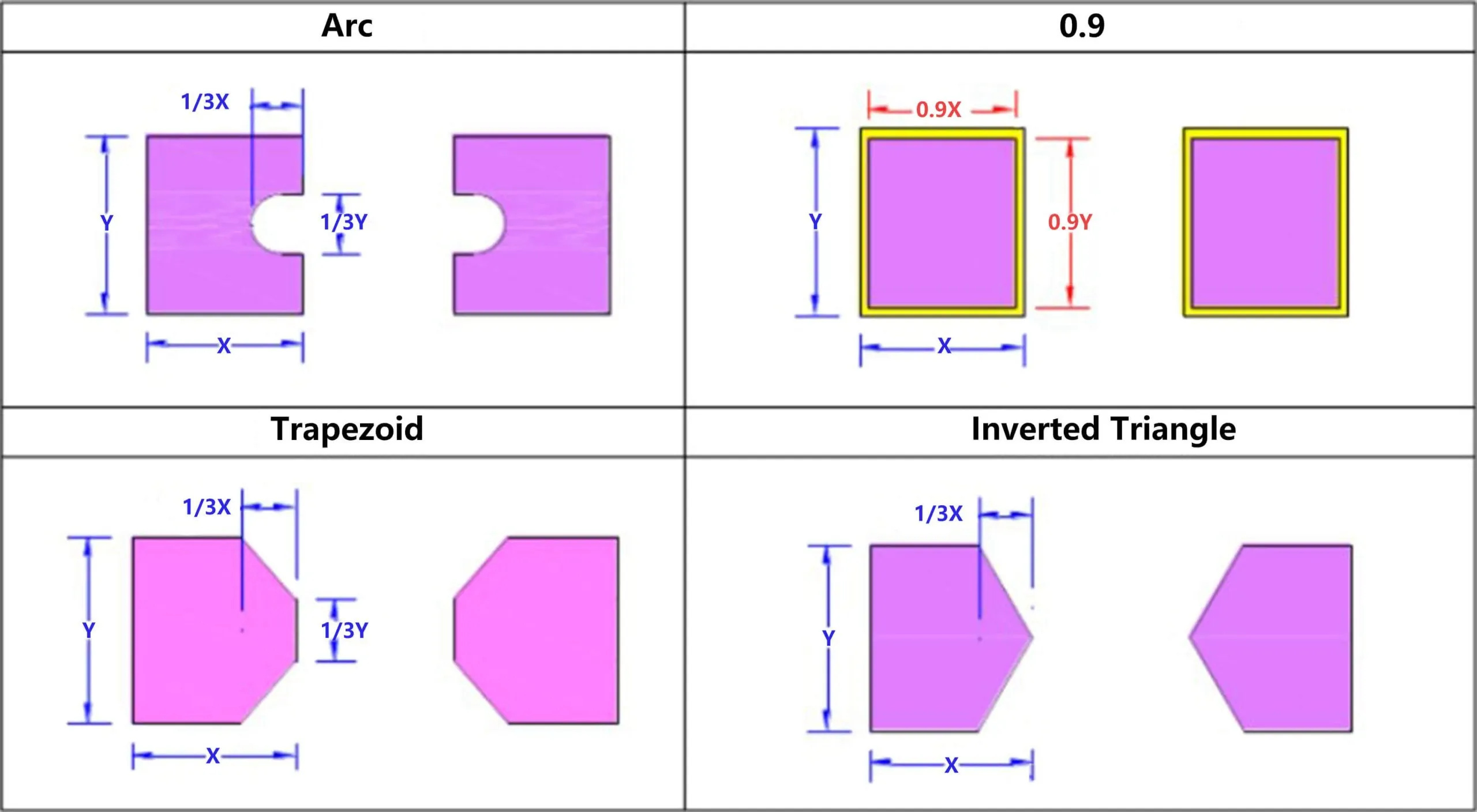
Fine pitch stencil design starts with selecting foil thickness matched to the smallest pitch, often 0.10 to 0.13 mm for 0.4mm components to maintain favorable area ratios. IPC-7525 guidelines recommend aperture widths 90 to 95 percent of pad size, with rounded corners at least 0.1 mm radius to prevent paste buildup. Trapezoidal or hourglass shapes reduce trapped paste volume, enhancing release over rectangular openings. Step-down stencils accommodate mixed technologies, thinning to 0.08 mm in ultra-fine areas while keeping 0.12 to 0.15 mm elsewhere. Surface treatments like nano-coatings minimize friction, boosting transfer efficiency above 75 percent.
Aperture spacing must exceed 0.15 mm to avoid bridging propensity. Fiducials on the stencil frame ensure repeatable alignment, critical for multi-panel arrays. Laser cutting precision below 5 microns supports these tolerances. Design files in Gerber or ODB++ format should include polarity marks and tension borders for printer compatibility. Validating designs via simulation software predicts volume deposition before fabrication. These elements collectively enable robust fine pitch stencil design tailored to production realities.
Optimizing Stencil Printers for 0.4mm Pitch Applications
Configuring a stencil printer for 0.4mm pitch requires fine-tuning alignment, speed, and pressure to balance fill completeness and clean release. Vision-based auto-alignment achieves plus or minus 12 micron accuracy, verified by fiducial recognition on both stencil and board. Squeegee speed around 40 to 60 mm per second prevents paste shearing, while snap-off heights of 0.8 to 1.2 mm avoid smearing. Pressure settings scale with blade length, typically 1 to 2 kg per 25 cm, adjusted via load cells for consistency across panels. Under-stencil wipe frequency every 5 to 10 prints uses vacuum or wet paper to remove residue without drying the paste.
Paste roll height, about 6 to 8 mm diameter, ensures even shear across the stencil. Printer software logs parameters for statistical process control, flagging drifts in volume or position. For high-volume runs, dual squeegees in opposing directions improve uniformity on large boards. Calibration routines, including height mapping, compensate for stencil tension variations. Implementing 2D or 3D solder paste inspection post-print rejects outliers early. These practices transform a stencil printer for 0.4mm pitch into a high-yield asset.
Identifying and Preventing Solder Paste Printing Defects
Solder paste printing defects manifest as bridging, where excess paste connects adjacent pads, often from thick stencils or high squeegee pressure. Insufficient paste volume appears as skips or low deposits, stemming from fast speeds or clogged apertures. Smearing occurs during stencil separation if snap-off is inadequate, leaving tails on edges. Pin-in-paste defects arise in through-hole areas from poor gasketing, while scooped centers indicate uneven squeegee contact.
Root causes trace to paste age, improper storage above 10 degrees Celsius, or humidity swings altering rheology. IPC-610 classifies these against visual and dimensional criteria, guiding acceptability. Prevention involves daily paste kneading, stencil cleaning validation, and process capability studies targeting CpK above 1.33. Adjusting for board warpage with support pins mitigates distortion. Operator training on defect recognition accelerates root cause analysis. Systematic monitoring via SPI data correlates parameters to outcomes, enabling predictive tweaks.
- Bridging: Primary causes: thick stencil, high pressure. Prevention: use thinner foil and optimize area ratio per IPC-7525.
- Insufficient paste: Primary causes: low pressure, high speed. Prevention: tune to 40 to 60 mm/s and verify paste roll height.
- Smearing: Primary causes: poor snap-off, dirty stencil. Prevention: set around 1 mm snap-off and wipe every 5 prints.
- Scooping: Primary causes: uneven squeegee contact. Prevention: level blades and map stencil flatness.
Best Practices and Troubleshooting for Reliable Prints
Adhere to J-STD-001 requirements by validating solder volume against land patterns, ensuring 100 percent pad coverage without excess. Implement a maintenance schedule: inspect squeegees weekly, replace every 100,000 prints, and audit printer pneumatics monthly. Paste qualification tests check for slumping and balling before loading. For troubleshooting, isolate variables sequentially: first alignment, then parameters, using DOE matrices. If defects persist, audit stencil etch quality and consider electro polish for smoother walls.
Inline SPI with height and volume metrics provides real-time feedback, rejecting boards below 95 percent first-pass yield. Collaborate with stencil suppliers on design iterations based on production data. Document baselines for each job, scaling for panel count. These habits foster process robustness across shifts. Continuous improvement loops refine setups for evolving fine-pitch challenges.
Conclusion
Precision solder paste application via stencil printers defines success in fine-pitch PCB assembly, demanding expertise in design, operation, and defect mitigation. Key takeaways include tailoring fine pitch stencil design to IPC-7525 principles, tuning stencil printers for 0.4mm pitch with micron-level controls, and proactively addressing solder paste printing defects through data-driven practices. Engineers who integrate these elements achieve superior yields and reliability. Stay vigilant on parameters and maintenance to adapt to denser boards ahead. This mastery not only boosts efficiency but elevates overall assembly quality.
FAQs
Q1: What key factors define effective fine pitch stencil design for high-density PCBs?
A1: Fine pitch stencil design prioritizes thin foils of 0.10 to 0.13 mm for pitches like 0.4mm, trapezoidal apertures with area ratios above 0.66, and rounded corners to enhance paste release. IPC-7525 guides aperture sizing to 90 percent of pad width, preventing bridging. Surface nano-coatings reduce friction, while fiducials ensure alignment. Validate via simulation to predict volumes accurately. These elements minimize defects in production.
Q2: How can engineers select and set up a stencil printer for 0.4mm pitch components?
A2: Choose printers with vision alignment under 15 microns and 3D SPI integration for real-time verification. Set squeegee speed to 40 to 60 mm/s, pressure 1 to 2 kg per 25 cm blade, and snap-off 1 mm. Calibrate daily with height mapping to counter warpage. Use under-stencil wipes every 5 to 10 prints. Monitor CpK values above 1.33 for consistency. This setup yields reliable prints for demanding fine-pitch assemblies.
Q3: What are the most common solder paste printing defects and their fixes?
A3: Solder paste printing defects include bridging from excess paste, skips from low volume, and smearing from poor release. Fixes involve thinning stencils, optimizing speed-pressure balance, and frequent cleaning. Check paste rheology and humidity control to avoid slumping. IPC-610 criteria help classify issues. Implement SPI for early detection, targeting first-pass yields over 95 percent through iterative tuning.
Q4: Why does stencil thickness matter in preventing printing defects on fine-pitch boards?
A4: Stencil thickness directly impacts area ratio and transfer efficiency; thicker foils suit coarse pitches but cause bridging at 0.4mm. Use 0.12 mm max for fine features per guidelines. Thinner options improve release but risk fragility. Balance with aperture design for optimal volume. Troubleshoot by measuring deposits against specs, adjusting for mixed-tech boards with steps.
References
IPC-7525C — Stencil Design Guidelines. IPC, 2021
IPC-610H — Acceptability of Electronic Assemblies. IPC, 2019
J-STD-001H — Requirements for Soldered Electrical and Electronic Assemblies. IPC/JEDEC, 2020


