Introduction
In PCB manufacturing, depaneling represents a critical final step where individual boards are separated from production panels. Factories face the choice between mechanical routing and laser depaneling, each offering distinct capabilities suited to different production demands. Mechanical routing uses high-speed spindles to mill along predefined paths, while laser depaneling employs focused beams to ablate material precisely. Selecting the appropriate method ensures board integrity, minimizes defects, and aligns with production volumes and design complexities. This article compares these techniques from a factory perspective, highlighting laser depaneling advantages, PCB routing limitations, cost comparison depaneling machines, and the best depaneling method for FR4 materials. Engineers must evaluate stress levels, edge quality, and throughput to optimize their processes.
Understanding Mechanical Routing in PCB Depaneling
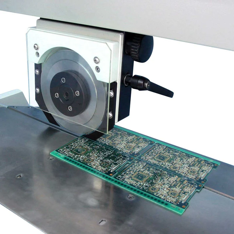
Mechanical routing involves a rotating carbide or diamond-coated bit that mills through the panel substrate along routing channels. Panels typically feature tabs or mouse bites to maintain stability during handling and assembly prior to depaneling. The process supports straight and curved cuts but requires sufficient clearance around boards to accommodate tool diameter and path. Factories often integrate automated routers with vision systems for alignment, enabling high-speed operations in rigid board production. However, the physical contact introduces challenges in maintaining flatness and avoiding contamination. IPC-A-600K provides guidelines on acceptable edge conditions post-depaneling, emphasizing the need for burr-free finishes.
Routing excels in high-volume scenarios where panels hold numerous identical boards. Operators secure the panel on a fixture, and the spindle follows fiducials or programmed paths to sever connections. Post-cut cleanup removes fiberglass dust, which can embed in components if assembly precedes depaneling. While effective for standard FR4 panels, the method demands regular tool changes due to wear from abrasive materials. Engineers appreciate its simplicity in setup for rectangular layouts but note constraints in intricate designs.
Principles of Laser Depaneling
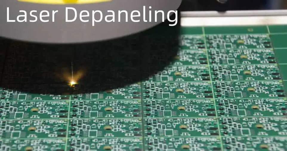
Laser depaneling utilizes a high-energy beam, often from CO2, UV, or fiber sources, to vaporize or melt material along the cut line without physical contact. The process follows a fiducial-aligned path programmed into the system software, allowing for complex geometries like tight curves or cutouts. Modern systems employ galvo scanners for rapid beam steering, achieving micron-level precision while minimizing heat-affected zones through pulse control. In factory settings, exhaust systems capture ablation byproducts, ensuring a clean environment compliant with quality standards. The non-contact nature preserves board stress levels, critical for multilayer stacks.
The laser interacts with FR4 epoxy by breaking molecular bonds, creating a narrow kerf that reduces material loss compared to mechanical bits. Beam parameters such as wavelength, pulse duration, and power density are tuned for substrate thickness and copper cladding. This adaptability suits varied panel configurations, from rigid to flex-rigid hybrids. Factories benefit from reduced fixturing needs, as vacuum hold-downs suffice without clamping pressure. Overall, the technology aligns with IPC-6012E specifications for rigid board performance by limiting mechanical deformation.
Laser Depaneling Advantages
Laser depaneling advantages shine in precision and stress-free separation, eliminating risks of microcracks or delamination common in mechanical processes. Without tool contact, boards experience no bending forces, preserving dimensional stability essential for subsequent SMT assembly. Factories report cleaner edges with tapered profiles that reduce snagging during handling, and the dust-free operation cuts post-process cleaning time significantly. For high-density panels, lasers enable tighter spacing between circuits, maximizing yield per panel array. This method proves superior for prototypes or low-volume runs with irregular shapes, where reprogramming routers would be inefficient.
Another key benefit lies in versatility across materials, handling FR4 thicknesses from 0.4mm to over 2mm without tool swaps. UV lasers excel on thin boards, minimizing charring, while CO2 suits thicker rigid panels. The process supports fiducial-less alignment via edge detection, streamlining setup in diverse production lines. Engineers value the traceability through cut logs, aiding root-cause analysis in quality control. Ultimately, these advantages translate to higher first-pass yields, aligning with factory goals for reliability.
PCB Routing Limitations
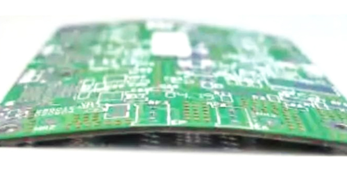
PCB routing limitations primarily stem from mechanical forces that induce stress, leading to warpage or bow in sensitive boards. The milling action flexes the panel, potentially cracking inner copper layers or vias in multilayer FR4 stacks. Dust generation necessitates thorough cleaning to prevent shorts in assembled units, adding cycle time and contamination risks. Tool wear accelerates with glass-filled epoxies, requiring frequent replacements that interrupt production flow. Curved paths demand larger radii due to bit size, limiting design freedom for compact layouts.
Fixturing challenges further compound issues, as thin panels may vibrate, causing inconsistent cuts or chipping. In high-mix environments, reprogramming for varied tab routings slows throughput compared to laser flexibility. Edge burrs often require secondary deburring, impacting IPC-A-600K acceptability criteria for Class 3 boards. Factories mitigate these by optimizing feed rates and coolant use, yet limitations persist for fragile or densely packed designs. Engineers must weigh these trade-offs against volume needs.
Cost Comparison of Depaneling Machines
Cost comparison depaneling machines reveals mechanical routers offer lower upfront investment, ideal for budget-conscious factories scaling rigid FR4 production. Operating expenses include bits, which wear quickly on abrasive substrates, and maintenance for spindles and vacuums. Lasers demand higher initial capital for optics and sources but feature minimal consumables, with diode lifetimes exceeding 10,000 hours in some configurations. Long-term savings emerge from higher yields and reduced rework, particularly in complex panels where routing scrap rates climb.
Throughput factors heavily: routers process panels faster in straight-line heavy layouts, amortizing costs over high volumes. Lasers lag in speed for simple jobs but excel in setups minimizing labor for intricate cuts. Energy use favors routers for short runs, while lasers efficiency improves with automation integration. Factories conduct total cost of ownership analyses, factoring yield impacts on IPC-6012E compliance. Ultimately, choice hinges on production profile, with hybrids emerging for balanced needs.
Best Depaneling Method for FR4
Determining the best depaneling method for FR4 depends on panel complexity, thickness, and stress tolerance. For standard multilayer FR4 up to 1.6mm in high-volume rigid production, mechanical routing prevails due to speed and established tooling. Laser depaneling advantages dominate for thin (<0.8mm) or high-density FR4 with fine-pitch components, avoiding warpage that compromises assembly. Complex outlines with internal cutouts favor lasers, enabling tabless designs that enhance automation.
Factory insights recommend hybrid panels: V-score straight edges with routed or laser tabs for optimized flow. FR4's glass reinforcement amplifies routing stress, so lasers preserve flatness per IPC standards. Prototyping suits lasers for rapid iterations without tooling costs. Engineers simulate stress via FEA to validate choices pre-production.
Practical Considerations and Best Practices
Select depaneling based on design rules: allocate 1.5mm minimum routing channels, tighter for lasers at 0.2mm. Integrate fiducials for alignment accuracy exceeding 50 microns. Post-depaneling inspections verify edge quality against IPC-A-600K, using microscopes for burrs or char. For lasers, optimize parameters to control heat-affected zones below 50 microns. Factories sequence depaneling after reflow to release lamination stresses first.
Best practices include panel optimization: symmetric layouts reduce warpage risk. Vacuum systems capture particulates, maintaining Class 100 cleanrooms. Operator training ensures safe laser handling per IEC guidelines. Track metrics like cycle time and yield to refine processes. Collaborative design reviews early flag depaneling constraints.
Conclusion
Choosing between routing and laser depaneling hinges on balancing precision, stress, cost, and volume in PCB production. Laser depaneling advantages excel in complex, sensitive FR4 applications, overcoming PCB routing limitations like mechanical damage. Cost comparison depaneling machines favors routers for scale, lasers for quality-driven runs. The best depaneling method for FR4 aligns with specific factory needs and standards compliance. Engineers prioritizing reliability invest accordingly, ensuring robust manufacturing outcomes.
FAQs
Q1: What are the main laser depaneling advantages over routing for FR4 PCBs?
A1: Laser depaneling advantages include non-contact cutting that minimizes stress and warpage, ideal for thin or multilayer FR4. It enables complex shapes with micron precision and generates no dust, reducing cleanup. Factories achieve higher yields on dense panels, aligning with IPC-A-600K edge requirements. This method suits prototypes and high-mix production effectively.
Q2: What are key PCB routing limitations in high-volume manufacturing?
A2: PCB routing limitations involve mechanical stress causing potential delamination or cracking in FR4 stacks. Dust production requires extensive cleaning, and tool wear increases downtime. Curved cuts demand wider channels, limiting density. Despite speed advantages, it risks non-conformance to IPC-6012E performance specs in sensitive designs.
Q3: How does cost comparison depaneling machines impact factory decisions?
A3: Cost comparison depaneling machines shows routers with lower entry costs and fast throughput for rigid FR4 volumes. Lasers incur higher upfront expenses but lower ongoing maintenance via no tools. Yield gains offset costs in complex jobs. Factories calculate TCO considering scrap and rework aligned with quality standards.
Q4: What is the best depaneling method for FR4 panels with fine-pitch components?
A4: The best depaneling method for FR4 with fine-pitch components is laser depaneling, offering stress-free separation and tight tolerances. It preserves flatness critical for SMT placement, avoiding routing-induced warpage. For standard volumes, hybrid routing works, but lasers ensure IPC compliance in demanding applications.
References
IPC-A-600K — Acceptability of Printed Boards. IPC, 2020
IPC-6012E — Qualification and Performance Specification for Rigid Printed Boards. IPC, 2017
IPC-2221 — Generic Standard on Printed Board Design. IPC, 2012


