Introduction
Surface mount technology (SMT) assembly traditionally depends on stencil printing to deposit solder paste precisely onto printed circuit boards (PCBs). This method ensures uniform paste volume for reliable reflow soldering, but it requires significant upfront investment in stencil fabrication and cleaning. For low volume SMT production, prototypes, or high-mix scenarios, these steps introduce delays and costs that can hinder efficiency. Stencil-free SMT assembly emerges as a viable alternative, leveraging methods like solder dispensing and jet printing to bypass stencils entirely. Engineers often question its feasibility due to concerns over precision and joint quality, yet advancements make it practical today. This article explores whether stencil-free SMT truly works, focusing on technical realities and implementation strategies.
What Is Stencil-Free SMT Assembly and Why It Matters
Stencil-free SMT refers to assembly processes that apply solder paste without a physical stencil, using contactless or needle-based deposition techniques instead. Primary methods include jet printing, where tiny droplets of paste are propelled onto pads, and solder dispensing, which extrudes paste through needles. These approaches suit alternative assembly methods tailored to specific production needs. In traditional stencil printing, setup changes demand new stencils, limiting flexibility for low volume SMT runs. Stencil-free options eliminate this, enabling rapid prototyping and small-batch production without tooling delays. For electric engineers managing diverse projects, this matters because it reduces lead times, cuts costs by up to 30 percent in low volume scenarios through avoided stencil expenses, and supports agile manufacturing.
The relevance grows in industries with frequent design iterations, such as consumer electronics and medical devices, where low volume SMT dominates. Engineers benefit from programmable deposition, allowing instant adjustments for pad sizes or component types without hardware swaps. Quality remains paramount, as joints must meet established criteria regardless of application method. This shift aligns with demands for leaner operations, minimizing waste from stencil storage and maintenance. Ultimately, stencil-free SMT empowers teams to handle complex boards with fine-pitch components more efficiently.
Technical Principles of Stencil-Free SMT
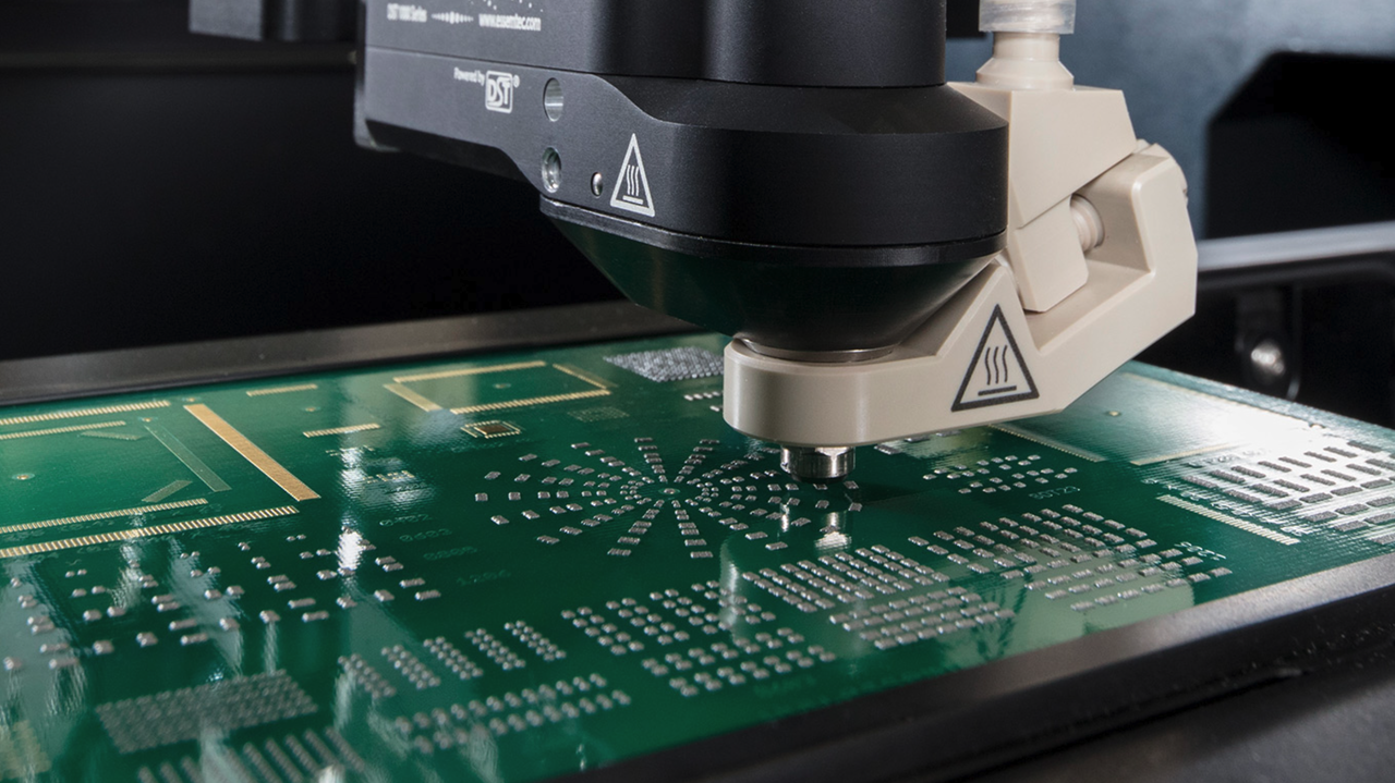
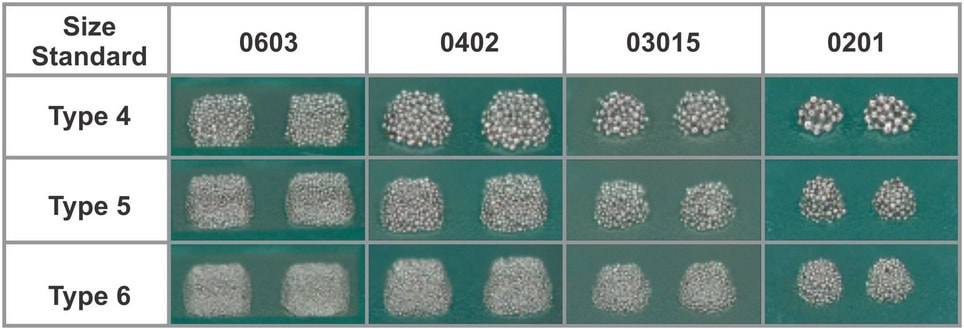
Jet printing operates on non-contact principles, using piezoelectric actuators or pneumatic systems to eject solder paste droplets at high speeds. Each droplet, typically 0.1 to 0.5 nanoliters, builds up the required volume by layering multiple shots per pad. This digital control allows pixel-like precision, ideal for irregular pad shapes or stepped components that challenge stencils. Paste rheology plays a key role, requiring Type 4 or finer particles for consistent ejection without clogging. Reflow profiles must account for the discrete deposit nature, potentially needing adjustments for optimal wetting.
Solder dispensing, conversely, uses volumetric pumps to extrude paste through needles, offering simplicity for larger deposits or adhesives. Precision depends on needle gauge and standoff distance, with Z-axis control preventing smearing. Both methods demand cleanroom environments to avoid contamination, as paste exposure increases compared to enclosed stencil printing. Post-deposition inspection verifies volume uniformity, often via laser height measurement or SPI systems. Assemblies produced this way must conform to IPC J-STD-001 requirements for soldered electrical and electronic assemblies, ensuring joint integrity through verifiable process controls.
In jet printing, frequency and drop speed influence throughput, with modern systems achieving hundreds of thousands of deposits per hour. Challenges arise from paste viscosity changes over time, necessitating agitation and temperature control. Dispensing suits hybrid applications, combining paste with epoxy for bottom-side components. These principles enable stencil-free SMT by replicating stencil volumes digitally, but success hinges on material-process synergy.
Practical Solutions and Best Practices for Stencil-Free SMT
Implementing stencil-free SMT starts with equipment selection suited to low volume SMT demands, prioritizing flexibility over raw speed. Jet printers excel for fine-pitch applications down to 0.3mm, while dispensers handle coarser features efficiently. Calibrate systems daily, focusing on drop volume repeatability through software fiducials for board alignment. Use solder pastes optimized for non-contact deposition, with low slump and high tack to hold components pre-reflow. Process validation involves statistical process control, monitoring deposit height variation below 10 percent.
For low volume runs, program deposition patterns directly from CAD files, enabling changeovers in minutes. Integrate with pick-and-place machines for seamless lines, reducing handling risks. Pre-reflow verification uses automated optical inspection to catch insufficient or excess paste early. Nitrogen reflow atmospheres enhance joint formation, mitigating oxidation in discrete deposits. Adhere to IPC-A-610 acceptability criteria for electronic assemblies, classifying solder joints visually post-reflow to confirm fillet formation and voiding limits.
Best practices include multi-head configurations for balanced throughput and hybrid lines pairing jet printing with traditional methods for mixed volumes. Train operators on paste handling to prevent air entrapment, which causes inconsistent jetting. For troubleshooting volume discrepancies, audit pump pressures and nozzle orifices regularly. These steps make stencil-free SMT reliable, particularly for alternative assembly methods in prototyping.
Challenges and Troubleshooting in Stencil-Free SMT
Despite advantages, stencil-free SMT faces hurdles like deposit inconsistency from paste settling, leading to bridging or tombstoning. Engineers troubleshoot by implementing inline agitation and viscosity monitoring, adjusting shear rates accordingly. Speed limitations in high-density boards require optimized paths, prioritizing critical components first. Fine-pitch challenges demand ultra-fine needles or high-frequency jetting, with standoff calibration preventing satellite droplets.
Common defects include insufficient volume on small pads, addressed by multi-pass deposition strategies. Excessive paste risks shorts, mitigated by precise dot counting and reflow profiling per J-STD-001 guidelines. Environmental factors, such as humidity, affect tackiness, so controlled storage below 10 degrees Celsius proves essential. Inspection post-placement catches offsets, with rework following IPC standards for minimal impact. For low volume SMT, logging process data facilitates root-cause analysis, refining parameters over runs.
Hybrid issues arise when mixing methods, like jetting paste and dispensing glue; synchronize viscosities to avoid crosstalk. Warpage on thin boards exacerbates alignment, necessitating fixture use during deposition.
Conclusion
Stencil-free SMT assembly proves possible and practical, especially through solder dispensing and jet printing for low volume SMT needs. These alternative assembly methods deliver precision comparable to stencils while slashing setup times and costs. By mastering paste selection, process controls, and standards like IPC J-STD-001 and IPC-A-610, engineers achieve reliable joints without traditional tooling. Challenges in volume control and speed exist but yield to targeted troubleshooting and validation. For electric engineers in prototyping or small-batch production, embracing stencil-free approaches unlocks flexibility and efficiency. Future advancements will further solidify its role in agile manufacturing.
FAQs
Q1: What is stencil-free SMT and how does it differ from traditional methods?
A1: Stencil-free SMT uses jet printing or solder dispensing to apply paste without stencils, offering digital control for precise deposits. Traditional stencil printing requires physical masks, suiting high volumes but slowing low volume SMT changes. This method excels in flexibility, reducing setup to software tweaks while meeting joint quality standards. Ideal for prototypes, it minimizes waste and supports complex geometries.
Q2: Is jet printing suitable for low volume SMT production?
A2: Yes, jet printing thrives in low volume SMT by eliminating stencil costs and enabling rapid design iterations. It handles fine-pitch components with droplet accuracy, building volumes layer by layer for uniform reflow. Throughput suits small batches, with quick programming from Gerber files. Process controls ensure IPC-compliant results, making it a go-to for high-mix environments.
Q3: What are common challenges in solder dispensing for SMT assembly?
A3: Solder dispensing risks volume variability from needle wear or paste inconsistencies, potentially causing reflow defects like insufficient wetting. Troubleshoot with pressure calibration and inline SPI for height checks. It complements jet printing in hybrid setups for adhesives. Best for coarser pitches in low volume SMT, always validate against acceptability criteria.
Q4: Can stencil-free methods meet industry soldering standards?
A4: Absolutely, stencil-free SMT adheres to IPC J-STD-001 for process requirements and IPC-A-610 for joint visuals, focusing on fillet and void specs. Independent of deposition, reflow optimization ensures compliance. Engineers verify via AOI and X-ray, confirming reliability for production.
References
IPC J-STD-001 — Requirements for Soldered Electrical and Electronic Assemblies. IPC, 2017
IPC-A-610 — Acceptability of Electronic Assemblies. IPC, 2017
J-STD-020 — Moisture/Reflow Sensitivity Classification for Nonhermetic Surface Mount Devices. JEDEC/IPC, 2014


