Introduction
Stencil printing forms the foundation of surface mount technology assembly, where precise solder paste deposition directly influences downstream processes like component placement and reflow soldering. Engineers often encounter challenges in achieving consistent paste volume and placement, which can lead to defects such as bridging or insufficient solder joints. Proper stencil printer setup ensures high first-pass yields and minimizes rework, critical for high-volume production runs. This guide outlines a systematic stencil printer setup procedure tailored for electrical engineers, focusing on key adjustments like squeegee pressure and stencil alignment. By following these steps, you can optimize performance while adhering to established industry practices. Mastering this process reduces variability and enhances overall assembly reliability.
Why Stencil Printer Setup Matters in PCB Assembly
Inaccurate stencil printer setup can result in solder paste defects that propagate through the entire assembly line, causing issues like tombstoning or open joints during reflow. For fine-pitch components, even minor misalignments exceed tolerances, leading to yield losses that impact production schedules and costs. Consistent setup aligns with quality standards such as IPC-A-610, which defines acceptability criteria for electronic assemblies, including solder paste deposits. Engineers benefit from a standardized approach that incorporates vision systems and parameter controls to maintain precision across batches. Ultimately, optimal setup supports scalability from prototypes to high-mix, low-volume manufacturing environments. Neglecting this step often reveals itself in inspection data, underscoring the need for methodical procedures.
Technical Principles of Stencil Printing
Stencil printing relies on the squeegee blade to shear solder paste across the stencil surface, filling apertures that correspond to PCB pads before clean release upon separation. Key mechanisms include paste rheology, which determines flow into small features, and stencil tension, which prevents warping during printing. Squeegee pressure forces paste into apertures while wiping excess, but excessive force can cause smearing or bridging on fine-pitch pads. Alignment precision, typically within 25 microns for modern processes, uses fiducials to register the stencil to the PCB, compensating for thermal expansion differences. Snap-off distance and speed control the paste release dynamics, influencing volume transfer efficiency. These principles, informed by guidelines like IPC-7525, ensure repeatable deposition volumes essential for reliable solder joints.
The interaction between print speed and pressure affects aperture fill: slower speeds allow better fill for high-aspect-ratio apertures, while higher pressures aid release but risk defects. Stencil thickness, often 100-125 microns for standard applications, balances volume control with release properties. Under-stencil cleaning maintains aperture cleanliness, preventing paste buildup that degrades print quality over cycles. Electrical engineers must consider board warpage, as uneven substrates distort alignment and paste transfer. Optimizing these variables through design of experiments yields process windows that accommodate material variations.
Step-by-Step Stencil Printer Setup Procedure
Step 1: Prepare Equipment and Materials
Begin by inspecting the stencil printer for cleanliness, verifying that the squeegee blades are free of nicks or wear and that under-stencil wipers function properly. Clean the stencil thoroughly using lint-free wipes and approved solvents to remove residual paste, avoiding abrasives that could alter aperture dimensions. Check solder paste for proper viscosity by performing a slump test if recent storage conditions warrant it. Ensure the PCB carrier or fixture accommodates the board size without inducing warp, and load support pins to match fiducial locations. Preheat paste if necessary to achieve optimal rheology, typically around room temperature for Type 4 or finer powders. Document initial conditions to track setup repeatability.
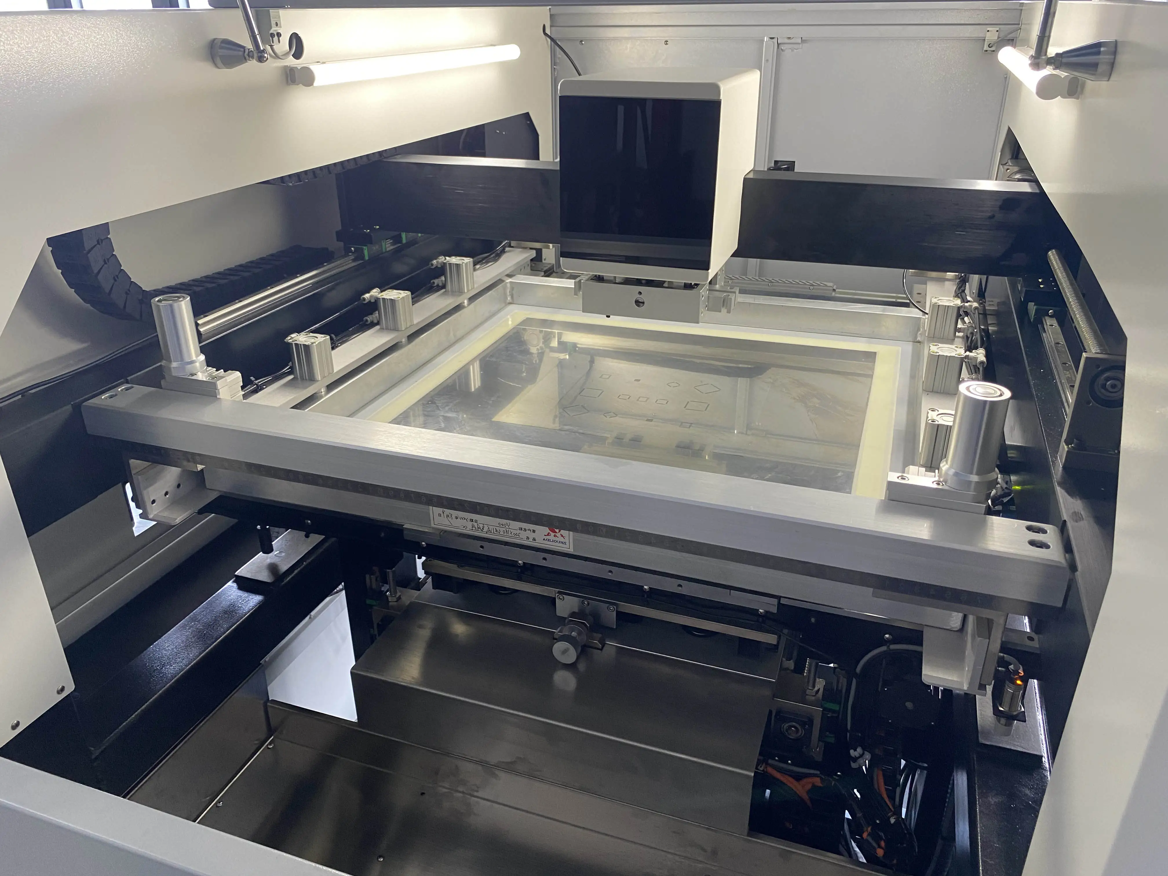
Step 2: Load and Tension the Stencil
Secure the stencil frame into the printer's clamps, ensuring even tension across all edges to prevent sagging, which distorts aperture alignment. Use a tension meter to verify uniform tension, aiming for values that maintain flatness per manufacturer specifications, often 15-25 N/cm. Register the stencil using tooling balls or pins if available, and activate the under-stencil cleaning system to confirm wiper contact without scratching the foil. Inspect apertures visually or with a microscope for debris or damage before proceeding. Proper tensioning supports consistent squeegee travel and paste release. This step sets the stage for precise stencil alignment process execution.
Step 3: Load the PCB and Perform Stencil Alignment
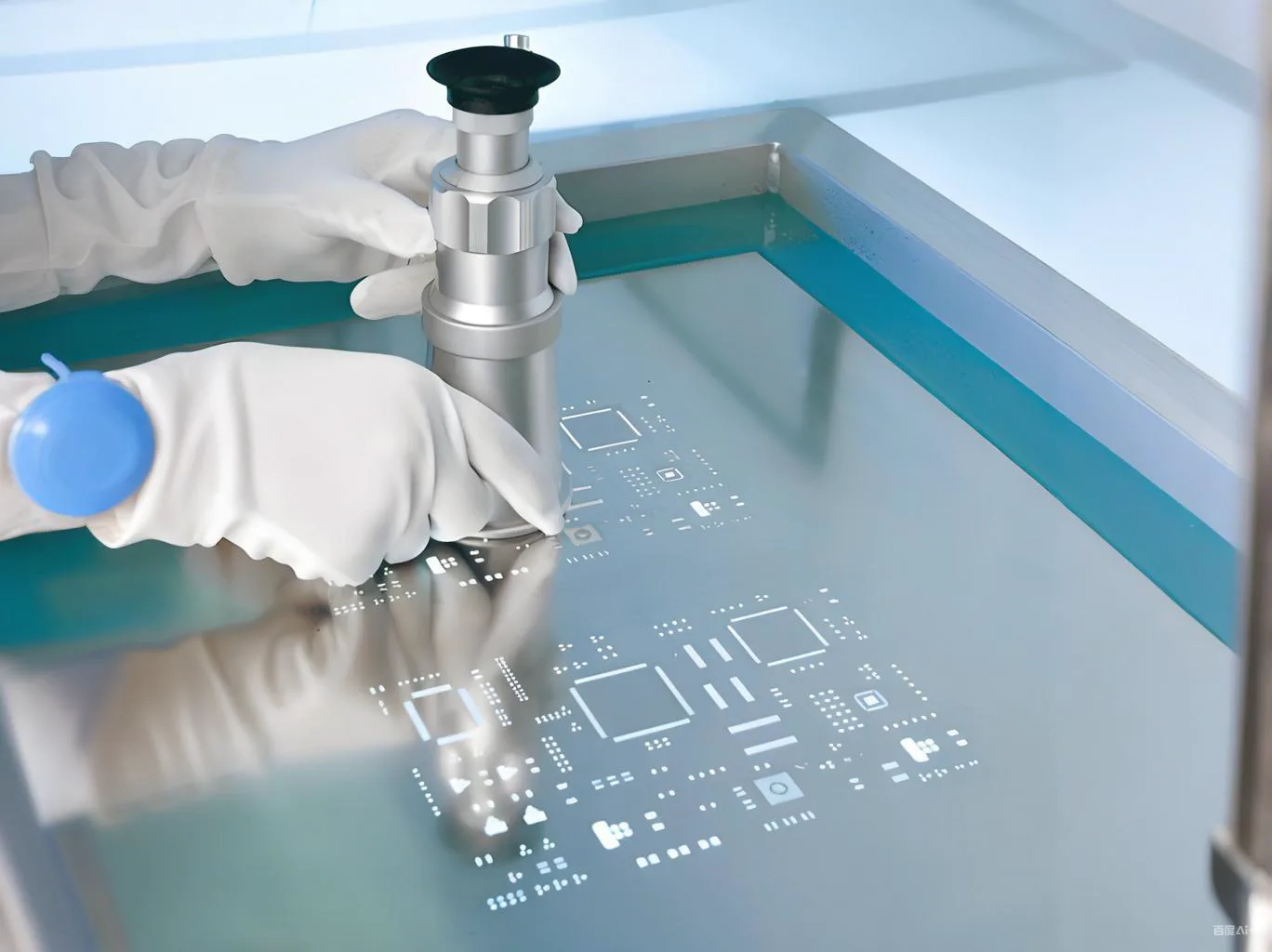
Place the bare PCB into the carrier, securing it with vacuum or edge clamps to minimize movement. Activate the printer's vision system to locate fiducials on both the PCB and stencil, typically three or more for orthogonal accuracy. Fine-tune X, Y, theta, and Z offsets until alignment errors fall below 20 microns, using live camera overlays for verification. Compensate for any stencil-to-board stretch by entering global offsets if the system supports it. Cycle the alignment multiple times to confirm stability under print conditions. Accurate stencil alignment process prevents offset paste deposits that lead to reflow defects.
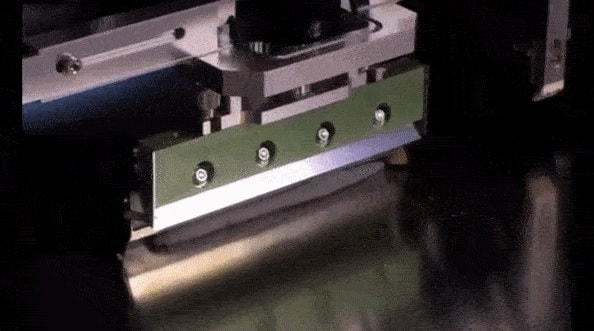
Step 4: Configure Print Parameters Including Squeegee Pressure Adjustment
Set initial squeegee speed to 20-50 mm/s for standard pastes, adjusting higher for finer powders to reduce settling. Establish squeegee pressure starting at 4-6 kg for a 300 mm blade length, scaling linearly with stencil width; monitor for clean wipes without stencil flex. Angle the blade at 55-60 degrees to optimize shear and roll dynamics. Define snap-off at 0.5-1.0 mm with a separation speed of 1-3 mm/s to promote clean release. Enable under-stencil cleaning every 1-3 prints, synchronized with squeegee passes. Perform squeegee pressure adjustment iteratively: print test boards, measure deposit height with SPI, and increment pressure in 0.5 kg steps until achieving 75-125% pad volume without bridging.
Step 5: Run Test Prints and Inspect
Execute 5-10 test prints on bare PCBs or inspection substrates, varying parameters if needed. Use solder paste inspection (SPI) to quantify volume, height, area, and placement offsets against IPC-A-610 Class 2 or 3 criteria. Analyze data for trends like low transfer efficiency, indicating insufficient pressure or poor release. Adjust based on defect modes: increase speed for bridging, reduce pressure for skips. Verify cleanliness by checking for residue post-print. Once stable, transition to production with statistical process control monitoring.
Step 6: Optimize and Maintain for Production
Profile the process window by varying speed, pressure, and snap-off in a factorial design, plotting transfer efficiency versus parameters. Implement auto-nozzle dispense for consistent paste volume on the squeegee. Schedule periodic stencil cleaning and tension checks to sustain performance. Train operators on the qualified setup recipe, including changeover procedures for different stencil thicknesses. Track long-term SPI data to refine the stencil printer setup procedure. This ensures sustained optimal performance across shifts.
Common Troubleshooting Issues and Fixes
Insufficient paste volume often stems from low squeegee pressure or high snap-off; incrementally increase pressure while monitoring bridging. Misalignment defects trace to fiducial occlusion or vision calibration drift; recalibrate cameras and clean optics. Bridging in dense areas requires slower speeds or finer paste, alongside enhanced under-stencil cleaning frequency. Stencil damage from over-tensioning causes inconsistent release; recheck tension and inspect apertures regularly. Warped PCBs exacerbate Z-axis issues; use adjustable supports or fixturing. Addressing these with root cause analysis maintains high yields.
Conclusion
Mastering the stencil printer setup procedure, from alignment to squeegee pressure adjustment, directly elevates PCB assembly quality and efficiency. By systematically preparing materials, aligning precisely, tuning parameters, and verifying with inspection, engineers achieve robust process control. Integrating standards like IPC-7525 ensures designs support optimal printing. Regular troubleshooting and optimization sustain performance amid material variations. Implementing these practices minimizes defects, accelerates time-to-market, and supports reliable electronics manufacturing.
FAQs
Q1: What is the ideal squeegee pressure for stencil printer setup?
A1: Squeegee pressure adjustment starts at 4-6 kg for standard 300 mm blades, scaled to stencil width, ensuring clean wipes without flexing. Test prints with SPI guide fine-tuning to 75-125% pad volume. Factors like paste type and aperture size influence final values; finer features demand lower pressures to avoid bridging. Consistent monitoring prevents variability.
Q2: How does the stencil alignment process impact print quality?
A2: The stencil alignment process uses fiducials and vision systems for sub-25 micron accuracy, preventing offset deposits that cause reflow opens or shorts. Poor alignment amplifies with board warp or thermal shifts. Verify with multiple cycles and global offsets for stability. This step underpins downstream placement precision.
Q3: What are key steps in the stencil printer setup procedure for fine-pitch assemblies?
A3: Key steps include equipment cleaning, stencil tensioning to 15-25 N/cm, fiducial-based alignment, parameter setting with moderate speed and pressure, and SPI-verified test prints. Focus on snap-off and cleaning frequency for small apertures. Iterate based on defect data for process windows. This ensures high transfer efficiency.
Q4: Why is under-stencil cleaning critical during setup?
A4: Under-stencil cleaning every 1-3 prints removes paste residue, maintaining aperture fill and release. Neglect leads to skips or inconsistent volumes. Synchronize with squeegee passes and use appropriate media. Regular checks sustain long-run performance.
References
IPC-7525B — Stencil Design Guidelines. IPC, 2011
IPC-7527 — Requirements for Solder Paste Printing. IPC, 2019
IPC-A-610H — Acceptability of Electronic Assemblies. IPC, 2019


