Introduction
Step stencils play a critical role in surface mount technology assembly by enabling precise solder paste deposition on printed circuit boards with mixed component heights. These stencils feature varying thicknesses across different areas, allowing thicker paste volumes for larger components like QFNs or connectors while maintaining fine-pitch accuracy for small devices such as 01005 chips or 0.3mm pitch BGAs. Selecting the appropriate stencil materials and finishes directly influences print quality, defect rates, and overall assembly yield. Engineers often face challenges like solder bridging or insufficient paste release, which can be mitigated through informed choices in these areas. This article explores stencil materials like stainless steel and nickel, along with key stencil finishes such as electropolishing, to guide practical decision-making for diverse PCB applications. By understanding these options, you can optimize processes and troubleshoot common issues effectively.
What Are Step Stencils and Why Do They Matter in SMT Assembly?
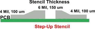
Step stencils, also known as multi-level or stepped stencils, consist of a thin metal foil with precisely machined apertures at different depths to accommodate varying solder paste requirements. In traditional uniform-thickness stencils, a compromise thickness leads to either excess paste for fine-pitch parts, causing bridging, or insufficient volume for larger components, resulting in poor joint formation. Step stencils resolve this by providing localized control, typically with steps ranging from 0.1mm to 0.15mm for fine pitch and up to 0.2mm or more for power devices. This capability is essential for modern high-density boards where components coexist across wide height ranges.
The relevance of step stencils grows with the trend toward miniaturized electronics and heterogeneous assemblies. They reduce the need for multiple stencils or manual paste adjustments, streamlining production and cutting costs. Poor step design can lead to paste smear during printing or alignment issues at transitions, emphasizing the need for robust materials and finishes. IPC-7525B provides guidelines on step geometry and keep-out zones to ensure reliable performance in such scenarios.
Key Stencil Materials: Stainless Steel and Nickel Compared
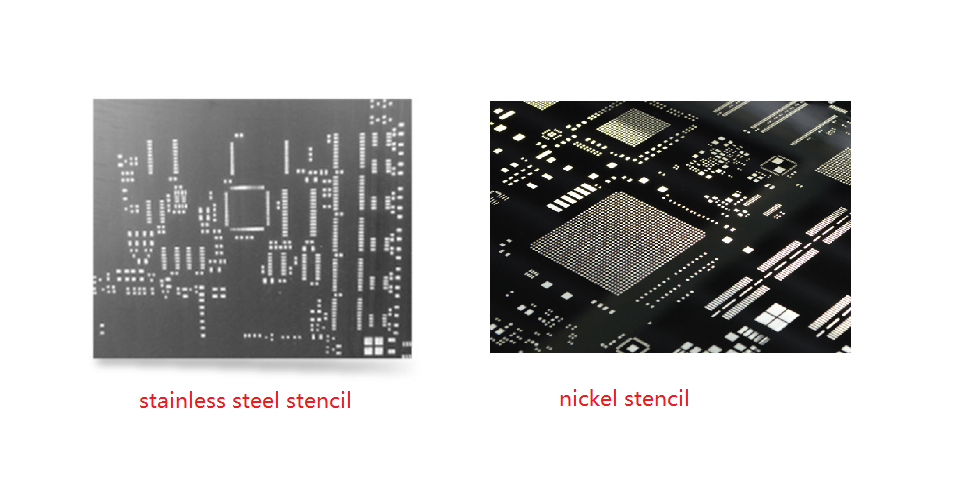
Stainless steel remains the most widely used material for step stencils due to its balance of durability, machinability, and affordability. Typically sourced as full-hard or fine-grain variants, it undergoes laser cutting or etching to form precise steps and apertures. Fine-grain stainless steel excels in thinner foils or aggressive step profiles, minimizing distortion during fabrication. However, it may exhibit higher friction compared to alternatives, potentially affecting paste release in high-speed printing.
Nickel, often produced via electroforming, offers superior precision for ultra-fine pitch applications below 0.4mm. Its inherently smoother surface and lower coefficient of friction facilitate cleaner paste transfer and reduced residue buildup. Nickel stencils demonstrate greater hardness than comparable stainless steel thicknesses, resisting wear over extended production runs. While more expensive upfront, nickel proves cost-effective for high-volume fine-pitch boards where yield is paramount.
When comparing stencil materials, consider the PCB layout complexity and component mix. Stainless steel suits general-purpose step stencils with moderate steps, providing versatility across many assemblies. Nickel shines in troubleshooting scenarios involving 01005 components or 0.3mm pitch devices, where aperture wall smoothness prevents bridging.
Understanding Stencil Finishes and Their Impact on Performance
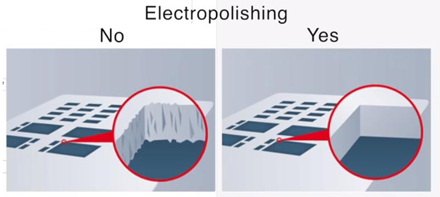
Stencil finishes refine the raw material surface to optimize solder paste behavior during printing. Electropolishing, an electrochemical process, removes microscopic burrs and peaks from aperture walls, yielding a mirror-like finish with sub-micron smoothness. This enhancement promotes consistent paste release, minimizes bridging on fine features, and extends cleaning intervals by reducing solder ball adhesion. Engineers appreciate electropolishing for its ability to maintain tolerances in step transitions, where mechanical stresses could otherwise degrade edges.
Beyond electropolishing, other stencil finishes address specific release challenges. Nanocoatings apply a thin, flux-repellent layer to the bottom surface and walls, preventing paste from sticking and allowing higher print speeds. Combining electropolishing with nanocoating maximizes benefits, as the polished base ensures geometric precision while the coating handles chemical interactions. These finishes prove vital in troubleshooting inconsistent volume transfer, a common issue in step stencil applications.
Selection hinges on paste type and printer setup. For lead-free pastes, which are more viscous, electropolished surfaces excel in uniform deposition. IPC-7525B recommends finish considerations aligned with aperture aspect ratios to avoid defects like insufficient solder joints.
Practical Guidance for Choosing Materials and Finishes
Evaluate your application starting with component pitch and step height differentials. For boards with pitches above 0.5mm and steps under 0.05mm, stainless steel with electropolishing offers a reliable, economical choice. It handles most production volumes without excessive wear, and the finish ensures clean release even after thousands of prints. Monitor for signs of fatigue, such as rounded apertures, and schedule inspections accordingly.
Shift to nickel for pitches below 0.4mm or when troubleshooting persistent bridging despite optimized squeegee pressure. Nickel paired with electropolishing delivers the lowest friction, ideal for high-mix, low-volume prototypes where precision trumps cost. Test print yields early, adjusting step keep-out zones per guidelines to prevent paste bridging at transitions. In high-volume scenarios, factor in cleaning frequency; electropolished nickel reduces underwipe needs, boosting throughput.
Integrate finishes strategically based on process data. Electropolishing alone suffices for many stainless steel stencils, but add nanocoating if flux residue causes defects. Validate choices through volume transfer efficiency tests, targeting 100% first-pass yield. Avoid over-specifying; mismatched materials lead to warping or alignment errors during frame tensioning.
Common troubleshooting pitfalls include ignoring material grain direction in laser cutting, which amplifies step distortion in stainless steel. Align the cut path with the rolling direction for stability. For nickel, ensure uniform plating thickness to maintain step parallelism. Document printer parameters like snap-off distance alongside material specs for repeatable results.
Best Practices for Step Stencil Implementation
Adopt a systematic approach to specification. Review Gerber data for pad-to-aperture ratios, aiming for 80-90% reduction on fine features. Select stencil materials based on foil thickness; under 0.1mm favors nickel, while thicker steps leverage stainless steel strength. Apply electropolishing universally to baseline performance, reserving advanced coatings for yield-challenged lines.
During assembly trials, measure key metrics like bridge percentage and paste height variation across steps. Adjust squeegee speed and pressure iteratively, noting how stencil finishes influence behavior. Stainless steel may require slightly higher pressure for release, while nickel responds to lighter settings. Maintain stencil flatness below 0.025mm across the frame to prevent gapping.
For sustainability in production, prioritize durable combinations like electropolished fine-grain stainless steel, which withstands 50,000+ cycles. Store stencils in controlled environments to preserve finishes. Regular audits per IPC-7527 printing standards ensure ongoing compliance and defect minimization.
Conclusion
Choosing the right step stencil materials and finishes transforms SMT assembly from a potential bottleneck into a precise, efficient process. Stainless steel provides versatile, cost-effective performance for broad applications, while nickel targets ultra-fine pitch demands with exceptional smoothness. Electropolishing emerges as a cornerstone finish, enhancing release and longevity across both materials. By aligning selections with PCB specifics and leveraging guidelines like IPC-7525B, engineers can troubleshoot effectively and achieve superior yields. Prioritize testing and documentation to refine choices, ensuring reliability in evolving designs.
FAQs
Q1: What are the primary stencil materials used in step stencil fabrication?
A1: Stainless steel and nickel dominate stencil materials for step stencils in SMT assembly. Stainless steel offers durability and ease of laser cutting for varied step heights, suiting most mixed-technology boards. Nickel provides lower friction and precision for fine-pitch components under 0.4mm. Select based on pitch and volume to optimize paste transfer and minimize defects like bridging.
Q2: How does stainless steel compare to nickel as a stencil material?
A2: Stainless steel excels in cost and machinability for general step stencils, handling thicker foils without distortion. Nickel, via electroforming, delivers harder surfaces and smoother walls, ideal for troubleshooting fine-pitch release issues. Stainless steel suits high-volume production, while nickel prevents wear in precision applications. Test both for your printer's paste compatibility.
Q3: What role does electropolishing play in stencil finishes?
A3: Electropolishing smooths aperture walls to sub-micron levels, improving solder paste release and reducing cleaning needs in step stencils. It eliminates burrs from laser cutting, preventing bridging on fine features and step transitions. This finish enhances stainless steel and nickel alike, boosting yield in high-density assemblies. Combine with other coatings for flux-heavy pastes.
Q4: When should you choose electropolishing for stencil finishes?
A4: Opt for electropolishing on stencil finishes when facing inconsistent paste volume or bridging in step stencils. It creates a burr-free, low-friction surface critical for pitches below 0.5mm and mixed heights. Essential for both stainless steel and nickel, it extends stencil life and aligns with IPC guidelines. Avoid if budget constrains basic laser-cut needs.
References
IPC-7525B — Stencil Design Guidelines. IPC
IPC-7527 — Requirements for Solder Paste Printing Performance. IPC


