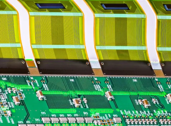
In the world of high-performance electronics, the gap between a conceptual design and a functional product is bridged by the assembly process. Rigid-Flex PCB Assembly represents one of the most sophisticated challenges in the Electronic Manufacturing Services (EMS) industry. By combining the structural stability of rigid boards with the versatile interconnectivity of flexible circuits, rigid-flex technology allows for three-dimensional product design, significantly reduced weight, and enhanced reliability.
However, the assembly of these hybrid systems is not a standard SMT (Surface Mount Technology) process. It requires specialized fixturing, precise thermal management, and a deep understanding of material behavior under stress. This guide provides an exhaustive analysis of the rigid-flex PCB assembly landscape, from substrate selection to final quality inspection.
1. The Foundation of Assembly: Material Science and Substrates
The journey of a successful Rigid-Flex PCB Assembly begins long before the first component is placed. It starts with the selection of the base materials. In a hybrid environment, the assembly must withstand multiple thermal cycles, and the materials used must maintain their structural integrity throughout.
Transitioning Beyond Standard Materials
While traditional rigid PCBs rely almost exclusively on FR-4 (Flame Retardant 4), rigid-flex systems require a mix of epoxy resins and polyimides. Standard FR-4 is often insufficient for the high-frequency and high-temperature demands of modern aerospace, medical, and telecommunications equipment. Engineers are increasingly turning to advanced laminates that offer lower dielectric loss and higher glass transition temperatures (Tg). To ensure the assembly can handle extreme environments, exploring advanced substrates for rigid-flex PCB assembly is essential for designers looking to move beyond FR-4 toward materials like LCP (Liquid Crystal Polymer) or high-speed polyimides.
Adhesiveless vs. Adhesive-Based Construction
In the assembly phase, moisture is the enemy. Traditional adhesive-based flex materials (using acrylic or epoxy adhesives) tend to absorb more moisture and have a higher Coefficient of Thermal Expansion (CTE). During reflow soldering, this moisture can turn into steam, leading to delamination or "popcorning." Modern high-reliability assembly processes favor adhesiveless laminates, which are thinner, more thermally stable, and significantly less prone to moisture-related defects during the reflow stage.
2. Design for Manufacturability (DFM): Ensuring Assembly Success
A rigid-flex board that looks perfect on a CAD screen can become a nightmare on the assembly line if DFM principles are ignored. DFM in Rigid-Flex PCB Assembly is about anticipating how the physical board will behave as it moves through pick-and-place machines, reflow ovens, and cleaning stations.
Critical DFM Parameters
-
Stiffener Placement: Components should never be placed on a flexible section unless it is backed by a stiffener. During assembly, the pressure of the placement head can deform the flex, leading to misaligned components or broken solder joints.
-
Panelization and Tooling: Flexible circuits are "floppy" by nature. To be assembled in high-volume SMT lines, they must be panelized with rigid borders or placed into custom-designed assembly pallets (carriers) that hold the flex sections flat and tensioned.
-
Trace Transition: Traces moving from the rigid section to the flex section must be reinforced with teardrops. If the transition is too abrupt, the mechanical stress of assembly and handling can cause the copper to crack at the interface. Establishing a rigorous design for manufacturability (DFM) in rigid-flex PCB assembly is the only way of ensuring a smooth production process, preventing costly mid-run revisions and maximizing manufacturing yield.

3. Signal Integrity and Impedance Control
As data rates increase, the assembly must act as a transparent medium for high-speed signals. Rigid-Flex PCB Assembly introduces a unique variable: the signal must travel across two different dielectric materials (FR-4 and Polyimide). If the impedance is not matched across this boundary, signal reflections and EMI (Electromagnetic Interference) will degrade the system's performance.
Handling High-Speed Signals
In the assembly of high-speed systems, the dielectric constant (Dk) of the material must be consistent. Because polyimide typically has a lower Dk than FR-4, the trace width must be precisely calculated and etched to maintain a standard 50-ohm or 100-ohm impedance. During assembly, any excess solder or poorly placed via can create a "discontinuity" that causes data loss. The precision of the assembly process directly dictates the final performance; understanding the impact of impedance control on signal integrity in high-speed rigid-flex PCB assembly is vital for maintaining high-speed signal integrity in complex, data-heavy applications.
4. The Specialized Assembly Process Flow
The actual assembly of a rigid-flex board involves several specialized steps that go beyond a standard SMT line.
A. Pre-Assembly Baking
Because polyimide is hygroscopic (it absorbs water from the air), rigid-flex boards must undergo a rigorous baking cycle before assembly. Typically, boards are baked at 120°C for several hours to remove any latent moisture. Failure to do this almost always results in delamination during the high-heat reflow process.
B. Fixturing and Palletization
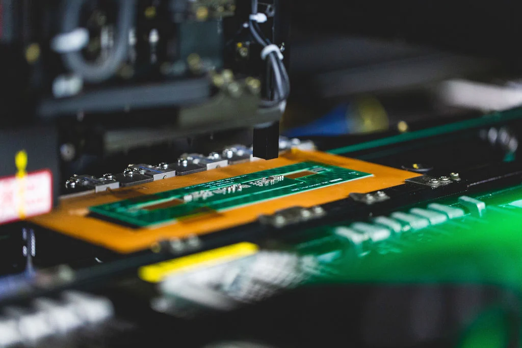
Since the flexible portion cannot support its own weight, the board is placed into a Solder Pallet or an Assembly Carrier. These fixtures are usually made of ESD-safe composite materials or aluminum. They use vacuum suction or mechanical clamps to hold the flex sections perfectly flat, allowing the Solder Paste Inspection (SPI) and Pick-and-Place machines to function with high precision.
C. Solder Paste Application
The use of fine-pitch components (BGAs, 0201s) requires highly accurate stencil printing. In rigid-flex assembly, the stencil must account for the slight height differences between the rigid and flex sections. Step-stencils are often used to ensure the correct volume of solder paste is deposited across different topographical levels of the board.
D. Reflow Profiling
Rigid-flex boards have a high "thermal mass" in the rigid sections and a very low thermal mass in the flexible sections. A standard reflow profile might overheat the flex while underheating the rigid areas. Assemblers must develop a specialized thermal profile using thermocouples to ensure every solder joint reaches the liquidus temperature without damaging the delicate polyimide substrate.
5. Soldering Techniques: SMT, PTH, and Manual
While SMT is the primary method for Rigid-Flex PCB Assembly, many mission-critical boards require Plated Through-Hole (PTH) components for mechanical strength, especially for connectors that will be repeatedly mated.
-
Reflow Soldering: Used for SMT components. It is the most common method but requires the aforementioned thermal profiling.
-
Selective Soldering: Used for PTH components on boards where the flexible sections might be heat-sensitive. This allows the machine to solder specific pins without exposing the entire board to a wave of molten solder.
-
Manual Soldering: Often required for final attachments or for adding stiffeners with pressure-sensitive adhesives (PSA). This requires highly skilled technicians, as polyimide can easily melt if the soldering iron temperature is not strictly controlled.
6. Post-Assembly: Cleaning and Protection
Once the components are soldered, the assembly must be cleaned of any flux residue. This is particularly important for rigid-flex boards because flux trapped in the "crevices" of the transition zones can cause corrosion over time.
Conformal Coating
To protect the assembly from moisture and dust, a conformal coating is often applied. However, the flexible portions of the board must remain flexible. Assemblers must use "masking" techniques to ensure that the coating is only applied to the rigid areas and the component bodies, leaving the "bend zones" of the flex circuit free to move without cracking the coating.
7. Quality Control and Testing (Inspection)
Given the high value and critical nature of rigid-flex boards, the inspection phase is rigorous.
-
Automated Optical Inspection (AOI): Used to check for component presence, orientation, and solder bridge defects.
-
X-Ray Inspection: Essential for BGAs and other bottom-terminated components where the solder joints are not visible. It is also used to check the internal registration of the flex layers within the rigid board.
-
Flying Probe Testing: Provides electrical verification of the traces. Because rigid-flex boards can have complex 3D shapes, the flying probe’s ability to move in 3D space is a major advantage.
-
Flex Testing: In some cases, a sample from the assembly lot is subjected to a "bend test" to ensure that the assembly process has not made the copper traces brittle.
8. Strategic Value: Why Invest in Rigid-Flex Assembly?
The complexity of Rigid-Flex PCB Assembly comes with a higher price tag compared to traditional interconnects. However, the return on investment (ROI) is found in the System-Level Cost Reduction.
-
Assembly Efficiency: By replacing 5 rigid boards and 4 wire harnesses with a single rigid-flex assembly, the final product assembly time is reduced from hours to minutes.
-
Reliability: 90% of electronic failures occur at the connector or cable interface. Rigid-flex eliminates these connectors, creating a far more robust product.
-
Miniaturization: It allows for the creation of devices like "swallowable" medical cameras or ultra-thin foldable smartphones that would be physically impossible with standard PCB technology.
9. Conclusion: The Path to Zero-Defect Assembly
Rigid-Flex PCB Assembly is the pinnacle of modern manufacturing integration. It requires a synergy between material science, mechanical design, and high-precision electronics assembly. By focusing on advanced substrates, implementing rigorous DFM principles, and maintaining strict impedance control, manufacturers can produce high-yield, high-reliability systems.
As we look toward the future of 6G, AI-driven hardware, and space exploration, the role of rigid-flex assembly will only expand. Success in this field belongs to those who view the assembly not as a series of steps, but as a holistic engineering challenge where every micron and every millisecond of heat matters.
FAQs
Q1: Why is a pre-assembly baking cycle required for rigid-flex boards?
A1: Polyimide, the primary material used in the flexible sections, is highly hygroscopic, meaning it absorbs moisture from the atmosphere. If these boards are not baked to remove moisture before they enter the high-heat reflow oven, the trapped water will expand rapidly into steam. This causes "popcorning" or delamination, where the layers of the PCB physically separate, destroying the board.
Q2: Can I use standard conformal coating on a rigid-flex assembly?
A2: You can use standard coating materials (like acrylic, silicone, or urethane), but the application method must be specific. If the coating is applied to the "bend zones" of the flexible section, it will crack when the board is folded, potentially damaging the traces underneath. In rigid-flex assembly, the flexible areas are usually masked off so that only the rigid, component-heavy areas are coated.
Q3: What are the biggest challenges in soldering components to flexible sections?
A3: The two main challenges are mechanical stability and thermal management. Flexible sections are thin and can warp under the heat of a soldering iron or reflow oven, leading to misaligned pads. Additionally, the flex material dissipates heat much faster than the rigid sections, making it difficult to maintain a consistent temperature for a high-quality solder joint without damaging the substrate.