Introduction
Flux plays a pivotal role in electronics assembly by enabling clean, strong solder joints that withstand operational stresses. Without proper flux action, oxides on metal surfaces hinder solder wetting, leading to weak connections prone to failure over time. In PCB reliability contexts, flux influences joint strength through its activation during reflow or wave soldering processes. Engineers often troubleshoot flux-related issues when assemblies exhibit premature degradation under humidity or thermal cycling. This article explores the mechanisms linking flux and solder joints to long-term performance, offering practical guidance for optimizing solder joint reliability.
Understanding Flux and Its Role in Solder Joint Formation
Flux is a chemical agent applied before soldering to remove oxides, promote wetting, and prevent re-oxidation during heating. Common types include rosin mildly activated fluxes, no-clean formulations with low residue potential, and water-soluble variants requiring post-process cleaning. In electronics assembly, flux integrates into solder paste or applies separately via spraying or dipping, directly affecting joint formation. Proper flux selection ensures uniform solder flow, forming reliable intermetallic bonds between solder, pad, and component lead. Mismatches in flux activity can result in incomplete wetting, compromising joint strength from the outset.
No-clean fluxes, designed for minimal residue, dominate modern high-volume production due to reduced cleaning steps. These rely on rosin or synthetic resins that activate at soldering temperatures around 220 to 260 degrees Celsius. Water-soluble fluxes offer higher activity for challenging surfaces but demand thorough rinsing to avoid conductivity risks. Each type balances cleaning power against residue impact on PCB reliability, guiding engineers in process decisions.
Mechanisms Behind Flux's Influence on Solder Joint Reliability
Flux enhances solder joint reliability by facilitating oxide removal and alloy flow, creating void-free joints with optimal fillet shapes. During reflow, activated flux decomposes, releasing gases that must vent fully to prevent voids weakening joint strength. Residual flux, if hygroscopic, absorbs moisture, initiating electrochemical reactions that degrade the joint over time. Flux corrosion manifests as dendritic growth or pitting on copper pads, accelerating under bias voltage and high humidity conditions common in field use.
Inadequate flux volume leads to poor wetting, forming brittle cold joints susceptible to mechanical fatigue. Excessive flux traps air or residues under components, promoting creep corrosion that erodes joint integrity. Thermal profiles influence flux performance; underheating leaves unactivated residues, while overheating volatilizes activators prematurely. These mechanisms underscore why flux and solder joints demand precise process control for sustained PCB reliability.
Standards like IPC J-STD-001 outline flux requirements to ensure consistent joint quality across assemblies. Engineers evaluate flux via surface insulation resistance testing to predict long-term behavior.
Flux Residues and Corrosion Risks in Electronics Assembly
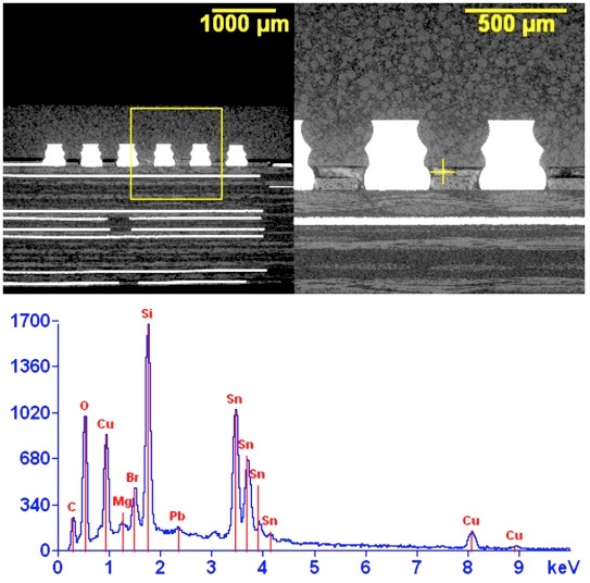
Flux residues pose the primary threat to solder joint reliability when not managed properly. Benign residues from no-clean fluxes should appear clear and non-tacky post-reflow, but incomplete drying under low-profile components fosters corrosion. Hygroscopic residues draw moisture, enabling ion migration that bridges adjacent conductors, causing shorts. Flux corrosion accelerates in harsh environments, reducing joint strength through base metal dissolution.
Visual inspection reveals white powdery residues indicating halide activation failures, often linked to water-soluble fluxes without cleaning. Cross-sectional analysis shows residue entrapment at the heel or toe of gull-wing leads, stressing the joint during thermal expansion. Humidity bias testing simulates these failures, highlighting flux formulation's role in ECM resistance.
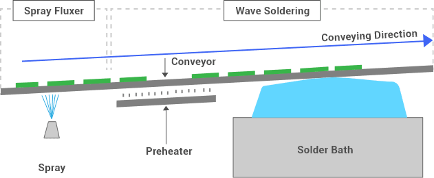
Process variables like conveyor speed in wave soldering affect residue distribution, with turbulence splashing flux onto non-targeted areas. Engineers troubleshoot by mapping residue patterns to reflow zones, adjusting nitrogen purging to minimize oxidation and residue persistence.
Factors Affecting Flux Performance and Joint Strength
Several factors modulate flux efficacy in maintaining solder joint reliability. Flux classification per industry guidelines, such as activity level and halide content, dictates suitability for lead-free or tin-lead alloys. High-activity fluxes excel on oxidized surfaces but heighten corrosion risk if residues linger. Solder paste formulations integrate flux at optimized ratios, typically 10 to 12 percent by weight, influencing printability and reflow dynamics.
Board finish types, from HASL to ENIG, interact differently with flux; immersion silver demands low-residue options to curb creep. Reflow atmosphere control reduces flux demand, preserving joint strength by limiting residue formation. Preheat stages activate flux gradually, preventing splatter that undermines uniformity.
IPC-A-610 provides acceptability criteria for flux residues, ensuring they do not compromise electrical performance. Non-adjacent integration of such standards reinforces process verification without redundancy.
Temperature-humidity exposure reveals flux weaknesses; no-clean types pass SIR thresholds above 100 megaohms under bias. Engineers prioritize flux matching assembly class, from consumer to high-reliability aerospace.
Best Practices for Optimizing Flux in Electronics Assembly
Select flux compatible with process and environment, favoring no-clean for cleanroom operations to streamline throughput. Verify flux against J-STD-004 classifications, ensuring low halide content for halide-free mandates. Apply precise volumes via stencil printing or sprayers, avoiding over-application that breeds residues.
Implement robust reflow profiling with peak temperatures holding flux activation without degradation. Post-reflow, inspect under magnification for residue uniformity, using UV fluorescence for hidden contaminants. For water-soluble fluxes, deploy inline cleaning with deionized water and dryers to eliminate conductivity paths.
Conduct process capability studies correlating flux parameters to joint strength metrics like shear force. Nitrogen reflow atmospheres enhance wetting, reducing flux reliance and boosting reliability. Regular flux potency checks via dip tests maintain consistency across lots.
Troubleshooting Common Flux-Related Reliability Failures
Spot early flux issues through field returns showing intermittent opens tied to corrosion. White residues signal no-clean flux under-activation; extend preheat to resolve. Dendrite formation under components points to trapped residues; optimize stencil design for better paste release.
HAST or THB testing accelerates failures, linking ECM to flux ionics. Shear testing quantifies joint strength degradation, guiding flux swaps. Cross-contamination from mixed flux types erodes reliability; segregate lines rigorously.
Log thermal profiles against failure modes, adjusting ramp rates for complete flux burnout. Collaborate with suppliers on residue analysis, but rely on in-house IPC-trained inspectors for verdict.
Conclusion
Flux profoundly shapes solder joint reliability, balancing oxide removal against residue risks in electronics assembly. Engineers achieve PCB reliability by selecting appropriate flux types, refining processes, and adhering to standards like IPC J-STD-001 and IPC-A-610. Proactive troubleshooting prevents flux corrosion, ensuring joint strength endures environmental stresses. Implementing these practices yields robust assemblies with extended service life, minimizing field failures.
FAQs
Q1: How does flux corrosion affect solder joint reliability?
A1: Flux corrosion arises from activated residues absorbing moisture, triggering electrochemical migration that bridges pads and weakens joints. This degrades joint strength, leading to opens or shorts in humid environments. Mitigation involves residue-free fluxes or thorough cleaning, per IPC-A-610 criteria, preserving PCB reliability in electronics assembly.
Q2: What role does flux play in improving joint strength during reflow?
A2: Flux removes oxides for optimal wetting, promoting uniform solder flow and intermetallic layer formation critical to joint strength. Proper activation prevents voids, enhancing mechanical integrity. Engineers monitor profiles to ensure flux efficacy, directly boosting solder joint reliability in high-volume production.
Q3: Why choose no-clean flux for electronics assembly?
A3: No-clean flux minimizes post-soldering cleaning, reducing costs while leaving benign residues that support long-term PCB reliability. Ideal for tight clearances, it avoids water damage risks. Test via SIR to confirm suitability, aligning with flux and solder joints best practices.
Q4: How can engineers test flux impact on PCB reliability?
A4: Conduct SIR, ECM, and corrosion tests under bias and humidity to evaluate residues. Shear and thermal cycling assess joint strength post-flux exposure. Correlate results to process tweaks, ensuring compliance with J-STD-001 for robust electronics assembly outcomes.
References
IPC J-STD-001G — Requirements for Soldered Electrical and Electronic Assemblies. IPC, 2017
IPC-A-610H — Acceptability of Electronic Assemblies. IPC, 2020
J-STD-004D — Requirements for Soldering Fluxes. IPC, 2020


