Introduction
In the fast-evolving field of electronics, high-speed rigid-flex PCB assembly plays a pivotal role in enabling compact, reliable, and efficient designs for advanced applications. These hybrid boards combine the structural stability of rigid sections with the adaptability of flexible regions, making them ideal for industries like aerospace, medical devices, and telecommunications. However, maintaining high-speed signal integrity in such complex structures poses significant challenges. A critical factor influencing performance is rigid-flex PCB impedance control. Without precise management, signal reflection problems can degrade system reliability. This article explores the intricate relationship between controlled impedance routing and signal integrity, delving into technical principles, practical solutions, and industry best practices. Aimed at electrical engineers, the content provides actionable insights to ensure optimal performance in high-speed designs.
Rigid-flex designs introduce unique challenges due to their mixed construction. Rigid sections often house high-density components, while flexible regions accommodate bending and folding. Transitions between these areas can disrupt impedance if not carefully managed. Poor impedance matching in rigid-flex boards risks signal degradation, electromagnetic interference, and system failures. For engineers, understanding and implementing impedance control is not just a design choice but a necessity for ensuring high-speed signal integrity in modern electronics.
What Is Impedance Control and Why It Matters in Rigid-Flex PCBs
Impedance control refers to the deliberate design of a PCB's transmission lines to maintain a consistent characteristic impedance. This parameter, measured in ohms, determines how electrical signals propagate through traces. In high-speed rigid-flex PCB assembly, where signals often exceed frequencies of 1 GHz, maintaining controlled impedance routing is essential to prevent distortions. Mismatched impedance can lead to signal reflection problems, causing data loss or timing errors in critical systems.
Rigid-flex designs introduce unique challenges due to their mixed construction. Rigid sections often house high-density components, while flexible regions accommodate bending and folding. Transitions between these areas can disrupt impedance if not carefully managed. Poor impedance matching in rigid-flex boards risks signal degradation, electromagnetic interference, and system failures. For engineers, understanding and implementing impedance control is not just a design choice but a necessity for ensuring high-speed signal integrity in modern electronics.
Technical Principles of Impedance Control in High-Speed Designs
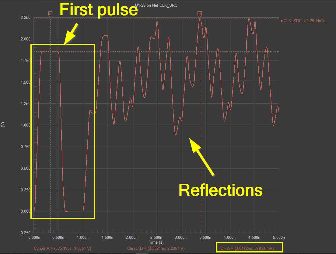
Impedance in a PCB trace is influenced by several factors, including trace width, thickness, dielectric constant of the substrate, and proximity to reference planes. In high-speed rigid-flex PCB assembly, signals behave as transmission lines, where any mismatch in impedance can cause reflections. These reflections occur when a signal encounters a change in impedance, sending part of the energy back toward the source. This phenomenon, often termed signal reflection problems, disrupts data integrity and increases noise.
The characteristic impedance of a trace must match the source and load impedances to minimize reflections. This principle, known as impedance matching in rigid-flex designs, requires precise calculations and simulations during the design phase. Standards such as IPC-2141A provide guidelines for designing controlled impedance traces, emphasizing the importance of consistent dielectric properties and trace geometries. In rigid-flex boards, maintaining uniformity across rigid and flexible sections is particularly challenging due to varying material properties.
Another key consideration is the dielectric stack-up. The choice of materials with stable dielectric constants and low loss tangents is crucial for high-speed signal integrity. Variations in material thickness or composition between rigid and flexible regions can alter impedance. Engineers must also account for the skin effect at high frequencies, where current concentrates on the trace surface, increasing effective resistance. Proper stack-up design and material selection are foundational to achieving controlled impedance routing in these hybrid boards.
Challenges to Signal Integrity in Rigid-Flex PCB Assembly
High-speed signal integrity in rigid-flex PCBs faces multiple threats beyond impedance mismatch. Crosstalk, where adjacent traces interfere with each other, becomes prominent at high frequencies. This issue is amplified in flexible sections where traces may be closely spaced to accommodate bending. Additionally, electromagnetic interference from external sources or internal switching noise can corrupt signals if shielding is inadequate.
Signal reflection problems are particularly acute at transitions between rigid and flexible areas. These junctions often involve changes in dielectric thickness or trace routing, disrupting impedance continuity. Loss of signal integrity can manifest as jitter, timing skew, or complete data corruption, especially in protocols like USB 3.0 or PCIe that demand precise timing. Standards such as IPC-6013D outline performance criteria for rigid-flex boards, stressing the need for consistent manufacturing processes to mitigate these risks.
Temperature variations and mechanical stress also impact impedance control. Flexible regions subjected to repeated bending may experience material fatigue, altering electrical properties over time. Engineers must anticipate these environmental factors during design to ensure long-term reliability of high-speed signal integrity.
Practical Solutions for Impedance Control in Rigid-Flex Designs
Achieving controlled impedance routing in rigid-flex PCBs requires a multi-faceted approach. Below are key strategies tailored for electrical engineers working on high-speed designs.
- Accurate Stack-Up Design: Begin with a well-planned layer stack that maintains uniform dielectric properties across rigid and flexible sections. Use simulation tools to predict impedance based on trace dimensions and material characteristics. Adherence to guidelines in IPC-2141A ensures reliable outcomes.
- Trace Geometry Optimization: Adjust trace width and spacing to match the target impedance. In flexible areas, consider wider traces or additional ground planes to compensate for thinner dielectrics. Consistent geometry minimizes signal reflection problems.
- Material Selection: Choose substrates with stable dielectric constants and low loss for high-frequency applications. Ensure compatibility between rigid and flexible materials to avoid impedance discontinuities at transitions.
- Transition Management: Design smooth transitions between rigid and flexible zones by tapering traces or adjusting layer counts gradually. This reduces abrupt changes that impair impedance matching in rigid-flex boards.
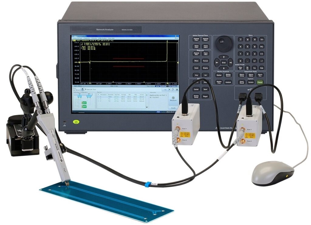
- Testing and Validation: Post-manufacturing testing using time-domain reflectometry can identify impedance mismatches. Standards like IPC-TM-650 provide test methods to verify controlled impedance routing.
Implementing these practices demands close collaboration between design and manufacturing teams to align on tolerances and material choices. Regular validation against industry standards ensures that high-speed signal integrity remains uncompromised.
Best Practices for Maintaining High-Speed Signal Integrity
Beyond impedance control, preserving high-speed signal integrity in rigid-flex PCB assembly involves broader design and assembly considerations. Ground planes should be continuous across rigid and flexible sections to provide a stable reference for signals. Avoid splitting ground planes under high-speed traces, as this can introduce noise.
Routing strategies also play a critical role. Minimize trace length differences in differential pairs to prevent timing skew. Keep high-speed traces away from edges or bends in flexible areas to reduce stress-induced impedance variations. Shielding sensitive signals with ground vias or copper pours can mitigate crosstalk and external interference.
During assembly, ensure precise alignment of layers to prevent misregistration, which can alter trace impedance. Standards such as IPC-A-600K offer visual and performance criteria for acceptable board assembly, guiding engineers in quality control. Post-assembly testing for signal integrity using eye diagrams or bit error rate analysis helps confirm design success.
Troubleshooting Signal Integrity Issues in Rigid-Flex Assembly
When high-speed signal integrity issues arise, systematic troubleshooting is essential. Start by examining impedance mismatches using measurement tools as outlined in IPC-TM-650. Look for discontinuities at rigid-flex transitions or areas of mechanical stress. Signal reflection problems often indicate abrupt changes in trace impedance, which can be traced to design or material inconsistencies.
Analyze crosstalk by reviewing trace spacing and ground plane coverage. Insufficient shielding or overly tight routing in flexible sections may require redesign. Environmental testing, simulating thermal cycles or bending stress, can reveal if material degradation affects impedance matching in rigid-flex boards over time.
Document findings and correlate them with design simulations to refine future iterations. This iterative approach, grounded in standards like IPC-6013D, builds robust designs resilient to high-speed challenges.
Suggested Reading: High-Performance PCB Assembly: Key Design Considerations 2026
Conclusion
Impedance control stands as a cornerstone of high-speed signal integrity in rigid-flex PCB assembly. By meticulously managing controlled impedance routing, engineers can mitigate signal reflection problems and ensure reliable performance in demanding applications. From stack-up design to material selection and post-assembly testing, every step influences the outcome. Adhering to established industry standards provides a framework for success, guiding designs toward optimal impedance matching in rigid-flex structures. As electronics continue to push boundaries of speed and complexity, mastering these principles becomes indispensable for innovation and reliability.
FAQs
Q1: How does rigid-flex PCB impedance control affect high-speed designs?
A1: Rigid-flex PCB impedance control ensures consistent signal propagation by matching trace impedance to source and load. In high-speed designs, mismatches cause reflections, leading to data errors or timing issues. Proper control, guided by industry standards, minimizes these risks and maintains signal quality across rigid and flexible sections.
Q2: What causes signal reflection problems in rigid-flex PCBs?
A2: Signal reflection problems occur due to impedance discontinuities, often at transitions between rigid and flexible areas. Variations in trace width, dielectric properties, or layer stack-up disrupt signal flow. Careful design and testing can identify and resolve these issues for better performance.
Q3: Why is impedance matching in rigid-flex boards critical for signal integrity?
A3: Impedance matching in rigid-flex boards prevents signal reflections and losses, crucial for high-speed signal integrity. Mismatched impedance at any point along a trace can distort signals, impacting data reliability. Consistent matching ensures clean transmission, especially in compact, hybrid designs.
Q4: How can engineers achieve controlled impedance routing in rigid-flex PCBs?
A4: Engineers can achieve controlled impedance routing by optimizing trace geometry, selecting stable dielectric materials, and designing uniform stack-ups. Simulation tools and adherence to standards help predict and verify impedance. Regular testing during and after assembly confirms design accuracy for high-speed applications.
References
IPC-2141A — Design Guide for High-Speed Controlled Impedance Circuit Boards. IPC, 2004.
IPC-6013D — Qualification and Performance Specification for Flexible and Rigid-Flexible Printed Boards. IPC, 2017.
IPC-A-600K — Acceptability of Printed Boards. IPC, 2020.
IPC-TM-650 — Test Methods Manual. IPC, Current Edition.


