Introduction
Surface mount technology (SMT) assembly relies heavily on reflow soldering to form reliable joints between components and the printed circuit board (PCB). During this process, the PCB substrate material plays a critical role in PCB thermal management by influencing how heat distributes across the board. Substrates with varying thermal properties can lead to differences in heat dissipation, potentially causing defects like uneven solder melting or board warpage. Electrical engineers must understand these effects to optimize SMT reflow profiling and ensure assembly yield. This article explores the mechanisms behind substrate influence on thermal performance, practical selection criteria, and troubleshooting strategies. By focusing on substrate thermal conductivity, engineers can enhance overall heat dissipation and assembly reliability.
Why PCB Substrate Material Matters for Thermal Performance in SMT Assembly
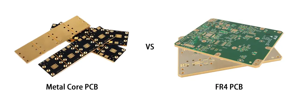
The choice of PCB substrate directly impacts thermal behavior during the high-temperature reflow cycle, where boards experience rapid heating and cooling. Standard epoxy-based substrates like FR-4 offer cost-effective solutions but exhibit limited substrate thermal conductivity, leading to localized hotspots around high-power components. In contrast, advanced options such as metal core PCBs provide superior heat spreading, which is essential for applications with dense component placement or elevated power dissipation. Poor thermal management can result in soldering defects, including incomplete reflow, bridging, or component tombstoning, compromising the entire assembly. Engineers prioritizing PCB thermal management must evaluate substrate properties early in the design phase to align with process capabilities. This consideration becomes even more vital as lead-free solders demand higher peak temperatures, amplifying the substrate's role in maintaining profile stability.
Related Reading: PCB Material Costs: Choosing the Right Substrate to Balance Performance and Price
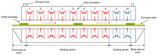
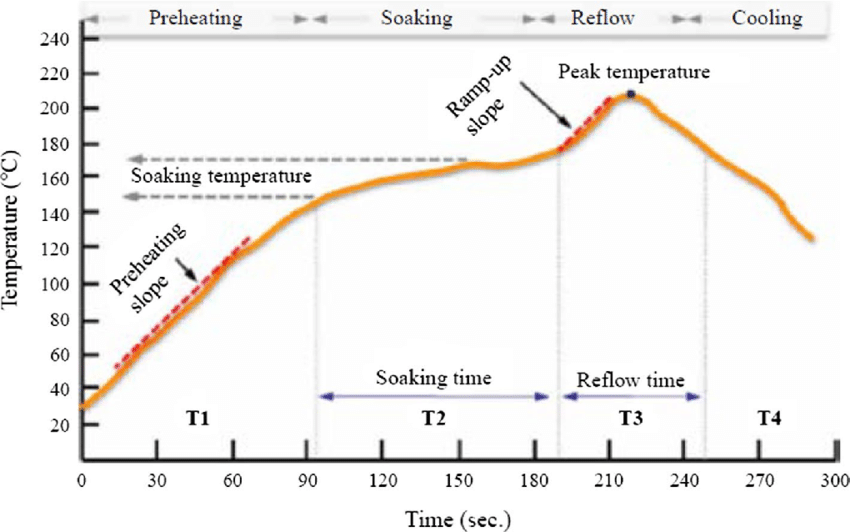
During SMT assembly, the reflow profile includes preheat, soak, reflow, and cooling phases, each sensitive to the board's thermal mass and conductivity. Substrates with low thermal conductivity slow lateral heat transfer, forcing reliance on copper traces and planes for dissipation, which may not suffice in complex boards. High-conductivity substrates mitigate these issues by uniformly distributing heat, reducing thermal gradients that cause stress. Industry standards like IPC-6012 emphasize material qualification for thermal reliability, underscoring the need for informed substrate selection. Ultimately, effective heat dissipation prevents long-term failures such as delamination or via cracking under operational stress.
Technical Principles: Substrate Thermal Conductivity and Heat Transfer in Reflow
Substrate thermal conductivity governs the rate at which heat moves through the PCB core during SMT reflow, directly affecting temperature uniformity. In FR-4 substrates, the glass-reinforced epoxy resin provides mechanical stability but poor in-plane conductivity, typically channeling heat primarily through the vertical z-axis via thicker copper layers or thermal vias. This limitation creates thermal shadows under large components, where slower heating delays solder paste activation. Metal core PCBs, featuring an aluminum or copper base insulated by a thin dielectric, excel in lateral heat spreading due to the metal's inherent high conductivity. During the ramp-up phase of SMT reflow profiling, such substrates achieve faster equilibrium, minimizing overshoot in peak zones and ensuring consistent liquidus time for all joints.
Heat dissipation mechanisms further differentiate substrates under reflow conditions. Low-conductivity materials trap heat in component pads, exacerbating coefficient of thermal expansion (CTE) mismatches between solder, components, and the board. This induces mechanical stresses that manifest as warpage, particularly in multilayer stacks with asymmetric copper distribution. High-conductivity metal core PCBs act as integrated heat sinks, rapidly conducting heat away from critical areas and into the board edges or fixtures. Convection-dominated reflow ovens amplify these effects, as air flow interacts differently with varying surface emissivity and thermal mass. Engineers modeling these dynamics often simulate transient profiles to predict gradient risks, aligning with JEDEC guidelines for reflow sensitivity.
Reflow profiling reveals substrate-specific challenges in the soak and reflow phases. Substrates with higher thermal mass, common in thicker metal core designs, require adjusted preheat ramps to avoid flux evaporation or oxidation. Conversely, thin FR-4 boards heat quickly but cool unevenly, risking thermal shock to sensitive components. Substrate properties influence the time above liquidus (TAL), a key metric for intermetallic formation and void minimization. Poor heat dissipation prolongs exposure to peak temperatures, potentially degrading laminate integrity or causing popcorn effects in moisture-laden boards. Understanding these principles enables precise oven zoning and conveyor speed tuning for optimal thermal performance.
Related Reading: The Reflow Soldering Process: A Practical Guide for Electrical Engineer’s Guide
Practical Solutions and Best Practices for Substrate Selection in SMT
Selecting the right substrate begins with assessing power density and component thermal requirements during PCB design. For moderate heat loads, high-Tg FR-4 variants suffice when augmented with embedded copper planes and filled vias for enhanced heat dissipation. In high-power scenarios, transitioning to metal core PCBs prevents hotspot formation, supporting reliable SMT assembly even in multi-zone reflow ovens. Always verify substrate compatibility with solder paste chemistry and alloy type to maintain flux activity throughout the profile. Collaborate with fabricators early to confirm material stack-ups that balance rigidity and thermal paths.
Optimizing SMT reflow profiling involves tailoring zone temperatures and durations to the substrate's characteristics. For low-conductivity FR-4, extend soak times to equalize temperatures across thermal masses, while shortening ramps for metal core boards to control peak exposure. Implement thermocouples strategically on test coupons representing the substrate's worst-case areas, such as corners or dense pad fields. Standards like IPC-7801 guide reflow process control, recommending profile validation with at least three runs per setup. Auxiliary techniques, including edge rails or forced-air assists, further improve heat dissipation uniformity.
Incorporate design-for-manufacturability (DFM) rules to leverage substrate strengths. Place high-dissipation components over reinforced thermal zones in metal core layouts, using blind vias to direct heat flow. For FR-4, distribute copper pours symmetrically to minimize warpage from asymmetric heating. Pre-bake boards per moisture sensitivity classifications to avert reflow-induced failures. Post-reflow inspections, including X-ray for voids and shear testing for joint strength, validate thermal performance. These practices ensure robust PCB thermal management across production scales.
Troubleshooting Thermal Issues Linked to Substrate Performance
Warpage tops the list of thermal defects in SMT assembly, often stemming from substrate-suboptimal heat dissipation during cooling. FR-4 boards prone to this exhibit bow or twist exceeding allowable limits, disrupting subsequent processes like test fixturing. Measure warpage with shadow moire or dial gauges post-reflow, correlating results to profile deviations. Adjust cooling gradients or add bow-compensating fixtures to counteract CTE-driven curvature. Metal core substrates resist this better due to their stiff base but may introduce unique stresses at dielectric-metal interfaces if not profiled correctly.
Hotspots around power devices signal inadequate substrate thermal conductivity, leading to over-reflow or charring. Profile data showing delta-T exceeds 10 degrees across the board confirms this; redistribute heat with vias or switch to higher-conductivity cores. Voids in solder joints arise from rapid substrate heating trapping gases, addressable by slower ramps or nitrogen atmospheres. Tombstoning in fine-pitch parts ties to uneven pad temperatures from poor lateral spread, mitigated by pad redesign and substrate upgrades. Systematic root-cause analysis, starting with profile audits, resolves most issues efficiently.
Component offset or bridging often traces to thermal gradients influenced by substrate mass. Thicker metal core boards demand conveyor slowdowns to match lighter FR-4 profiles. Use real-time infrared imaging for in-oven monitoring to pinpoint anomalies. If persistent, requalify the substrate per IPC-6012 criteria, ensuring thermal stability under repeated cycles. Document fixes in process control plans for repeatability.
Conclusion
PCB substrate material profoundly shapes thermal performance in SMT assembly, dictating heat dissipation efficiency and reflow profile fidelity. Low-conductivity FR-4 suits general applications when bolstered by design aids, while metal core PCBs excel in demanding thermal environments. Mastering substrate thermal conductivity enables precise SMT reflow profiling, minimizing defects and boosting yields. Electrical engineers benefit from proactive selection, profiling, and troubleshooting rooted in practical insights. Prioritizing PCB thermal management ensures reliable assemblies ready for field deployment. Adopt these strategies to navigate thermal challenges effectively.
FAQs
Q1: How does substrate thermal conductivity influence SMT reflow profiling?
A1: Substrate thermal conductivity determines heat spreading speed, affecting ramp rates and soak durations in reflow ovens. Low-conductivity materials like FR-4 create gradients requiring extended preheats for uniformity, while high-conductivity metal core PCBs allow aggressive profiles with reduced TAL risks. Profile adjustments prevent defects like voids or incomplete melts. Always validate with thermocouples on production-like boards for consistent results.
Q2: When should engineers choose metal core PCB for better heat dissipation?
A2: Opt for metal core PCBs in high-power density designs where FR-4's limited conductivity causes hotspots during SMT. These substrates spread heat laterally via the metal base, ideal for LED drivers or power amplifiers. They simplify thermal vias and sinks but increase board thickness and cost. Evaluate against operational temps and reflow constraints early.
Q3: What common thermal defects arise from poor PCB thermal management in assembly?
A3: Defects include warpage from CTE mismatches, solder voids from trapped gases, and tombstoning due to pad temperature deltas. These stem from uneven heat dissipation in low-conductivity substrates during reflow peaks. Troubleshoot via profile analysis and X-ray inspection, then refine zoning or add thermal aids. Proper management per industry standards yields defect-free joints.
Q4: How can SMT reflow profiling mitigate substrate-related thermal issues?
A4 : Tailor profiles to substrate mass: slower ramps for FR-4 to avoid overshoot, faster for metal core to prevent flux burnout. Monitor delta-T and TAL closely, using nitrogen for oxidation control. Test coupons simulate extremes, ensuring compliance across batches. This approach enhances heat dissipation reliability.
References
IPC-6012E — Qualification and Performance Specification for Rigid Printed Boards. IPC, 2017
IPC/JEDEC J-STD-020E — Moisture/Reflow Sensitivity Classification. JEDEC, 2014
IPC-7801 — Reflow Oven Process Control Standard. IPC, 2015


