Introduction
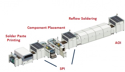
Reflow soldering remains the dominant method for attaching millions of surface-mount components daily in modern electronics manufacturing. The entire process chain (solder paste application, component placement, and controlled thermal profile) determines whether a board achieves 99.99% first-pass yield or suffers from tombstoning, voiding, head-in-pillow, or non-wetting defects. This article guides electrical engineers through each critical stage of SMT PCB assembly, offering practical, factory-floor insights into solder paste selection, stencil printing quality, pick-and-place accuracy, and reflow profile optimization to ensure consistent, high-yield production.
Step 1: Solder Paste Application – The Foundation
Solder Paste Types and Selection
- Type 3 (25–45 µm) → standard choice for 0603 and larger
- Type 4 (20–38 µm) → 0402, 0201, 0.5 mm pitch BGA
- Type 5/6 (5–15 µm) → 01005, 0.4 mm pitch and below, µBGA
No-clean, water-soluble, or ROL0/ROL1 flux classification must match downstream cleaning requirements and reliability needs.
Stencil Printing Best Practices
- 100–150 µm laser-cut, electro-polished stainless steel stencils
- Squeegee speed 20–80 mm/s, pressure 0.2–0.4 kg/cm
- Automated SPI (solder paste inspection) after printing is mandatory for <50 ppm defect rates
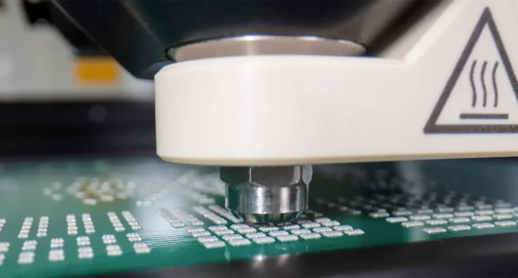
Step 2: High-Speed Pick-and-Place Machines
Placement Accuracy Requirements
- 0603/0402 → ±50 µm @3σ
- 0201/01005 → ±30 µm @3σ
- 0.4 mm BGA → ±25 µm @4σ
Common Placement Defects Caused by Poor Process
- Tombstoning → paste volume asymmetry or nozzle offset
- Skewed components → incorrect feeder setup or vision alignment failure
- Missing parts → vacuum pickup issues or tape advance errors
Modern pick-and-place machines with digital cameras and linear motors routinely place >100,000 components per hour with <10 ppm defects when properly maintained.
Step 3: The Reflow Soldering Process – Thermal Profile Development
Four Distinct Zones in a Reflow Profile
- Preheat (25–150 °C)
Ramp rate 1–3 °C/s to activate flux and prevent thermal shock. - Soak / Pre-reflow (150–180 °C, 60–120 s)
Evens out temperature across the assembly. - Reflow / Liquidus (peak 235–260 °C)
SAC305 liquidus = 217–221 °C. TAL 45–90 s. - Cooling
2–4 °C/s to prevent grain structure issues.
Lead-Free vs Leaded Profiles
Parameter: Peak temperature — Leaded: 215–235 °C — Lead-Free: 240–260 °C — Notes: Component max rating limits peak
Parameter: Time above liquidus — Leaded: 30–60 s — Lead-Free: 45–90 s — Notes: Longer TAL improves wetting
Parameter: Ramp rate — Leaded: ≤3 °C/s — Lead-Free: ≤3 °C/s — Notes: Prevents tombstoning
Parameter: Cooling — Leaded: 2–6 °C/s — Lead-Free: 2–4 °C/s — Notes: Faster cooling improves grain structure
Critical Defects and Their Root Causes
Defect: Tombstoning — Cause: Uneven heating — Prevention: Balanced apertures, <2 °C/s ramp
Defect: Head-in-pillow — Cause: Warped BGA — Prevention: Nitrogen reflow, fresh paste
Defect: Voiding — Cause: Flux outgassing — Prevention: Window-pane stencil, vacuum reflow
Defect: Non-wet — Cause: Low peak or TAL — Prevention: Extend TAL, raise peak
Defect: Bridging — Cause: Excess paste — Prevention: Reduce aperture size
Nitrogen vs Air Reflow
Air — Wetting: Good — Voiding: 10–25% — Cost: Low — Use: Consumer
Nitrogen (<500 ppm O₂) — Wetting: Excellent — Voiding: 3–8% — Cost: Higher — Use: High reliability
Profile Optimization Workflow Used on Factory Floor
- Attach 6–9 thermocouples
- Run initial linear ramp
- Adjust preheat zones to 1.5–2.5 °C/s
- Extend soak if ΔT >15 °C
- Ensure smallest component reaches 240 °C
- Verify TAL 60–75 s
- Confirm voiding <15% by X-ray
Conclusion
Mastering the reflow soldering process requires tight control at every stage: paste application, precise placement, and optimized thermal profile. While complexity varies among types of PCBs, the combination of Type 4/5 solder paste, SPI inspection, nitrogen-assisted reflow, and a well-tuned 10–12 zone oven commonly delivers yields exceeding 99.99%.
FAQs
Q1: How long can solder paste stay on a board before reflow?
A1: Maximum 4–6 hours at 20–25 °C and <60% RH for no-clean paste.
Q2: What is the ideal time above liquidus (TAL) for SAC305?
A2: 60–75 seconds. Less than 45 s risks non-wetting; over 90 s increases intermetallic growth.
Q3: Do I need nitrogen for consumer products?
A3: Not required for most commercial products.
Q4: Why do small 0201 components tombstone more easily than 0603?
A4: Smaller components have lower thermal mass and react faster to temperature differences.
References
IPC-J-STD-001H — Requirements for Soldered Electrical and Electronic Assemblies. IPC, 2020.
IPC-7095D — Design and Assembly Process Implementation for BGAs. IPC, 2018.
IPC-TM-650 2.6.27 — Thermal Stress, Convection Reflow Assembly Simulation. IPC, 2018.
IPC-J-STD-020E — Moisture/Reflow Sensitivity Classification. IPC/JEDEC, 2015.


