Introduction
Thermal management plays a critical role in the design and performance of mixed-signal printed circuit boards (PCBs). These boards integrate both analog and digital components, creating unique challenges in maintaining optimal operating temperatures. Excessive heat can degrade signal integrity, reduce component lifespan, and lead to system failures. Effective signal PCB thermal management ensures reliability and efficiency in applications ranging from telecommunications to industrial automation. This article explores the importance of thermal management for mixed-signal PCBs, delving into the underlying principles and offering best practices for thermal management. Aimed at electrical engineers, the content provides structured insights into mitigating heat-related issues while adhering to industry standards. By following these guidelines, designers can enhance performance and durability in their PCB projects.
What Are Mixed-Signal PCBs and Why Thermal Management Matters
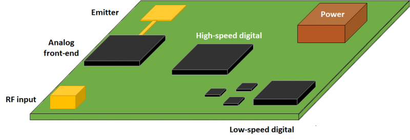
Mixed-signal PCBs combine analog and digital circuits on a single board, handling signals like audio, sensor data, and digital processing simultaneously. This integration often results in diverse power dissipation profiles across components. Digital circuits may generate sporadic high heat during switching, while analog components can produce consistent thermal output under load. Without proper signal PCB thermal management, temperature variations can cause noise interference, signal distortion, and component stress.
Thermal management matters because heat impacts both performance and reliability. Elevated temperatures can alter the electrical characteristics of sensitive analog components, leading to inaccuracies. Similarly, digital components may experience timing errors or failures if thermal limits are exceeded. Ensuring effective heat dissipation is vital for maintaining signal integrity and meeting design specifications. Poor thermal design also risks violating industry standards, potentially causing costly redesigns or field failures.
Technical Principles of Heat Generation in Mixed-Signal PCBs
Understanding the sources of heat in mixed-signal PCBs is the foundation of effective thermal management. Heat generation primarily stems from power dissipation in active components such as amplifiers, microcontrollers, and power converters. In digital circuits, rapid switching of transistors during operation causes dynamic power loss, proportional to frequency and load capacitance. Analog components, on the other hand, often dissipate heat through continuous current flow, especially in linear regulators or amplifiers under high gain.
Thermal resistance, measured from junction to ambient, dictates how efficiently heat is transferred away from components. High thermal resistance traps heat, raising junction temperatures. Additionally, the close proximity of analog and digital sections on mixed-signal PCBs can lead to thermal crosstalk, where heat from one section affects the performance of another. Board materials, copper trace density, and component placement further influence thermal behavior by affecting heat conduction and dissipation paths.
Environmental factors also play a role. Ambient temperature, airflow, and enclosure design impact how heat escapes the system. For instance, a sealed enclosure with limited ventilation exacerbates heat buildup. Engineers must account for these variables during design to predict thermal profiles accurately. Standards like JEDEC JESD51 provide guidelines for thermal characterization, helping to model and mitigate heat-related risks in PCB designs.
Challenges Specific to Mixed-Signal PCB Thermal Management
Mixed-signal PCBs face unique thermal challenges due to their hybrid nature. Analog components are highly sensitive to temperature-induced noise, requiring stable operating conditions. Digital components, while more robust, often generate significant heat spikes during peak operation, creating localized hot spots. These disparities can lead to uneven thermal distribution across the board, complicating signal PCB thermal management efforts.
Another challenge is the limited board space typical in compact designs. Placing heat-generating components close together increases thermal coupling, amplifying the risk of interference. Power supply circuits, often a major heat source, must be isolated from sensitive analog areas to prevent noise coupling through thermal gradients. Additionally, mixed-signal boards frequently operate in varied environments, from controlled indoor settings to harsh industrial conditions, demanding adaptable thermal solutions.
Best Practices for Thermal Management in Mixed-Signal PCBs
Implementing best practices for thermal management ensures the reliability of mixed-signal PCBs. Below are actionable strategies tailored for electrical engineers seeking optimal heat dissipation and signal integrity.
Optimize Component Placement
Strategic placement of components is a cornerstone of signal PCB thermal management. Position high-power components away from heat-sensitive analog circuits to minimize thermal interference. Group heat-generating parts near board edges or ventilation areas to facilitate heat escape. Ensure adequate spacing between components to prevent thermal coupling. Following layout guidelines from standards like IPC-2221B helps maintain clearances that support heat dissipation.
Use Thermal Vias and Copper Planes
Thermal vias are essential for transferring heat from component layers to inner or bottom copper planes. Place arrays of vias under high-power components to create low-resistance thermal paths. Connect these vias to large copper areas acting as heat sinks, spreading heat across the board. The multilayer circuit board benefits significantly from dedicated ground planes, which double as thermal conductors. Ensure vias comply with design rules in IPC-6012E for structural integrity.
Select Appropriate Board Materials
Material choice impacts thermal performance. Standard FR-4 materials have moderate thermal conductivity, suitable for low-power designs. For high-heat applications, consider materials with higher thermal conductivity, adhering to specifications in IPC-4101E. Balancing cost and performance is key, as advanced materials increase expenses but improve heat dissipation. Consult material data sheets and standards to match thermal requirements with design goals.
Incorporate Heatsinks and Cooling Solutions
Heatsinks are effective for dissipating heat from critical components like power regulators. Attach heatsinks directly to components or through thermal interface materials to enhance heat transfer. In constrained spaces, consider active cooling with fans if passive methods fall short. Ensure cooling solutions align with system-level thermal budgets and enclosure designs. Standards like JEDEC JESD51-2 offer test methods to validate cooling efficiency.
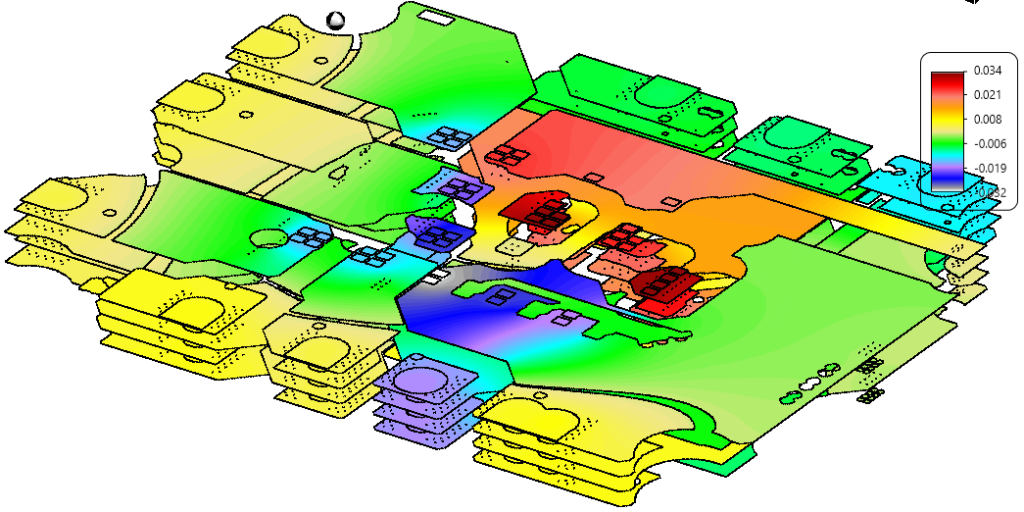
Simulate and Test Thermal Performance
Thermal simulation during the design phase identifies potential hot spots before fabrication. Use simulation tools to model heat flow based on component power dissipation and board layout. Validate simulations with physical testing, measuring temperatures under operating conditions. Adhere to JEDEC JESD51 guidelines for consistent thermal characterization. Iterative testing and redesign based on results ensure robust thermal management.
Manage Power Distribution
Efficient power distribution reduces heat generation. Use low-dropout regulators or switching converters to minimize power loss in voltage regulation. Decouple power supplies near components to stabilize voltage and reduce transient heat spikes. Route power traces with sufficient width to handle current without excessive resistive heating, following trace sizing rules in IPC-2221B. Proper power management directly supports best practices for thermal management.
Isolate Analog and Digital Sections
Thermal isolation between analog and digital sections prevents heat from digital components affecting analog performance. Use ground plane splits or physical separation to create thermal barriers. Route sensitive analog signals away from heat sources, ensuring minimal crosstalk. This approach preserves signal integrity while addressing thermal challenges unique to mixed-signal designs.
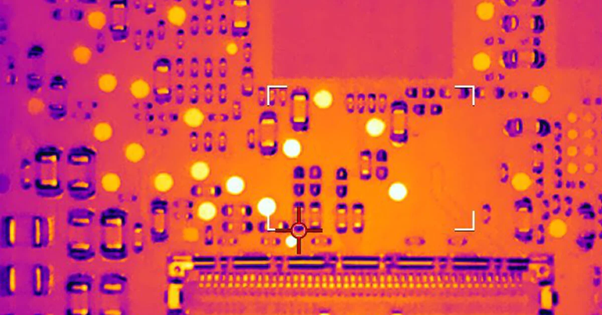
Troubleshooting Thermal Issues in Mixed-Signal PCBs
When thermal issues arise, systematic troubleshooting is essential. Start by identifying hot spots using thermal imaging cameras during operation. Compare measured temperatures against component specifications to pinpoint violations. If hot spots correlate with digital switching areas, consider reducing clock frequencies or adding local heatsinks. For analog sections showing drift, verify if nearby heat sources are the cause and adjust placement or shielding.
Check for inadequate thermal vias or insufficient copper area in multilayer boards. Adding vias or expanding ground planes can resolve localized heating. Review ambient conditions and enclosure ventilation, as restricted airflow often exacerbates issues. Ensure compliance with IPC-A-600K for board acceptability criteria, as manufacturing defects like delamination can impair heat dissipation. Document findings and iterate designs to prevent recurrence of thermal problems.
Suggested Reading: How to Overcome Challenges in Mixed Signal PCB Design
Conclusion
Effective thermal management for mixed-signal PCBs is vital for ensuring signal integrity and component reliability. By understanding heat generation principles and addressing the unique challenges of mixed-signal designs, engineers can implement best practices for thermal management. Strategies like optimized component placement, thermal vias, material selection, and simulation are grounded in industry standards and practical engineering. These approaches mitigate risks of thermal interference and extend the lifespan of critical systems. Adopting a proactive stance on signal PCB thermal management empowers designers to meet performance goals in demanding applications. With careful planning and adherence to guidelines, thermal challenges become manageable, paving the way for robust and efficient PCB designs.
FAQs
Q1: How does signal PCB thermal management impact mixed-signal designs?
A1: Signal PCB thermal management directly affects the performance of mixed-signal designs by preventing heat-induced noise and signal distortion. Analog components are particularly sensitive to temperature changes, which can alter their behavior. Digital sections, generating heat during switching, can interfere if not managed. Proper thermal strategies ensure stable operation across both domains, maintaining accuracy and reliability in applications.
Q2: What are the best practices for thermal management in compact PCB layouts?
A2: Best practices for thermal management in compact layouts include strategic component placement to avoid clustering heat sources, using thermal vias for heat transfer, and incorporating small heatsinks where possible. Select materials with better thermal conductivity if space constraints limit copper area. Simulation helps identify issues early. Following IPC-2221B layout guidelines ensures clearances support heat dissipation despite tight spacing.
Q3: Why is thermal simulation critical for mixed-signal PCB thermal management?
A3: Thermal simulation is critical for signal PCB thermal management as it predicts hot spots and temperature distribution before fabrication. It allows engineers to test layouts under various conditions, optimizing component placement and cooling solutions. Standards like JEDEC JESD51 guide accurate modeling. Early detection of thermal risks reduces redesign costs and ensures reliable performance in mixed-signal environments.
Q4: How can material selection improve thermal management in PCBs?
A4: Material selection enhances thermal management by determining how effectively heat conducts away from components. Standard FR-4 suits low-power designs, but high-performance materials with better thermal properties, per IPC-4101E, handle greater heat loads. Choosing appropriate substrates reduces junction temperatures, supporting best practices for thermal management. Balancing thermal needs with cost ensures efficient and sustainable PCB designs.
References
IPC-2221B - Generic Standard on Printed Board Design. IPC, 2012.
IPC-6012E - Qualification and Performance Specification for Rigid Printed Boards. IPC, 2020.
IPC-4101E - Specification for Base Materials for Rigid and Multilayer Printed Boards. IPC, 2017.
IPC-A-600K - Acceptability of Printed Boards. IPC, 2020.
JEDEC JESD51 - Methodology for the Thermal Measurement of Component Packages. JEDEC, 1995.
JEDEC JESD51-2 - Integrated Circuits Thermal Test Method Environmental Conditions - Natural Convection. JEDEC, 1995.


