Introduction
Through Hole Technology, commonly known as THT, remains a fundamental method for assembling electronic circuits, especially for hobbyists and applications requiring robust connections. While THT offers durability and ease of manual assembly, issues during soldering or component placement can lead to circuit failures. This article focuses on THT circuit troubleshooting, offering practical steps for identifying and fixing THT issues. Aimed at electronic hobbyists, the content provides actionable insights into common problems like poor solder joints and component misalignment. By understanding these challenges and applying effective electronic repair techniques, hobbyists can ensure reliable performance in their projects. Let’s explore the principles behind THT assembly issues and how to resolve them systematically.
What Is THT Assembly and Why It Matters
Through Hole Technology involves mounting electronic components by inserting their leads through pre-drilled holes on a printed circuit board (PCB) and soldering them to pads on the opposite side. This method, widely used since the mid-20th century, is valued for its mechanical strength, making it ideal for components subjected to stress or high power, such as connectors and large capacitors. For hobbyists, THT is accessible due to its compatibility with hand soldering and straightforward visual inspection.
The significance of THT lies in its reliability for prototyping and repair work. Unlike surface mount technology, THT components are easier to replace or adjust manually. However, improper assembly can lead to faults that affect circuit functionality. Mastering THT circuit troubleshooting ensures projects operate as intended, saving time and resources for electronic enthusiasts.
Technical Principles Behind THT Assembly Issues
Understanding the root causes of THT assembly problems is critical for effective troubleshooting. Several factors can disrupt the integrity of a THT circuit, ranging from soldering errors to mechanical stress. Below are the primary technical issues encountered in THT assembly.
Poor Solder Joints
Solder joints connect component leads to PCB pads, and their quality directly impacts circuit performance. A poor joint may result from insufficient heat, leading to a cold solder joint that appears dull and cracked. Alternatively, excessive heat can damage components or lift pads from the board. Contaminants like flux residue or oxidation on leads can also prevent proper adhesion.
Component Misalignment
Incorrect placement of components before soldering can cause misalignment. If leads are not fully inserted through holes, or if components are tilted, the solder may not form a reliable connection. This often happens when hobbyists rush the assembly process or work with poorly designed boards.
Thermal Stress and Damage
THT components, especially those with long leads, are susceptible to thermal stress during soldering. Prolonged exposure to high temperatures can degrade sensitive parts like diodes or integrated circuits. Additionally, repeated soldering and desoldering cycles can weaken the PCB substrate or traces.
Mechanical Stress on Leads
After assembly, physical stress on component leads due to bending or vibration can fracture solder joints or break internal connections. This is common in projects where boards are handled frequently or mounted in environments with movement.
Common THT Circuit Issues and Symptoms
Identifying the symptoms of THT assembly issues is the first step in troubleshooting. Here are the most frequent problems hobbyists encounter, along with their observable effects.
- Intermittent Connections: Circuits may work sporadically due to cracked or cold solder joints. This can manifest as flickering LEDs or inconsistent audio output.
- Complete Failure: A circuit may fail to power on if critical connections are broken or components are damaged during soldering.
- Overheating Components: Poor joints or misaligned parts can cause excessive current flow through unintended paths, leading to heat buildup.
- Visible Damage: Cracked solder, lifted pads, or burnt components are clear indicators of assembly errors or thermal stress.
Recognizing these signs early allows for targeted electronic repair, preventing further damage to the circuit.
Practical Solutions for Fixing THT Issues
Addressing THT assembly problems requires a systematic approach. The following solutions focus on fixing THT issues with tools and techniques suitable for hobbyists. Each step aligns with best practices to ensure reliable repairs.
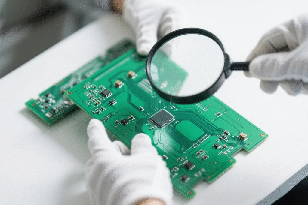
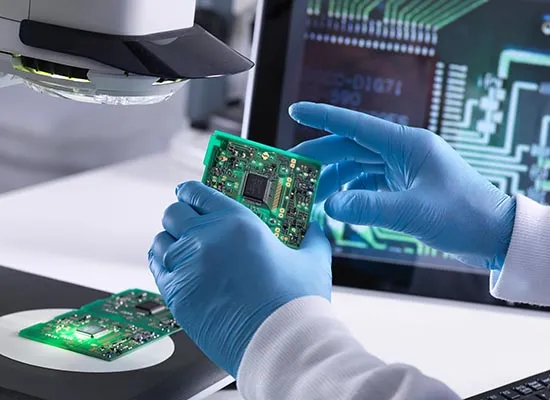
Step 1: Visual Inspection
Begin by examining the PCB under good lighting with a magnifying glass. Look for dull or cracked solder joints, misaligned components, or burnt areas. Check if leads are fully inserted through holes and soldered on the opposite side. This initial assessment often reveals obvious issues that need correction.
Step 2: Test Continuity with a Multimeter
Use a multimeter set to continuity mode to verify connections between component leads and PCB pads. If no beep is heard, the joint may be broken or incomplete. Test across suspected areas to pinpoint where the circuit fails. This method is effective for diagnosing intermittent connections.
Step 3: Reflow Solder Joints
For poor solder joints, reflow the connection by applying fresh solder and reheating with a soldering iron. Ensure the iron is at the correct temperature, typically between 300 to 350 degrees Celsius for lead-based solder, as per general industry guidelines. Clean the tip frequently to avoid contamination. Remove excess solder with a desoldering pump if needed.
Step 4: Replace Damaged Components
If a component shows signs of thermal damage or mechanical breakage, replace it. Use a desoldering tool to remove the old part without damaging the PCB. Insert the new component, ensuring proper orientation, and solder it in place. Double-check polarity for diodes and capacitors to avoid reverse installation.
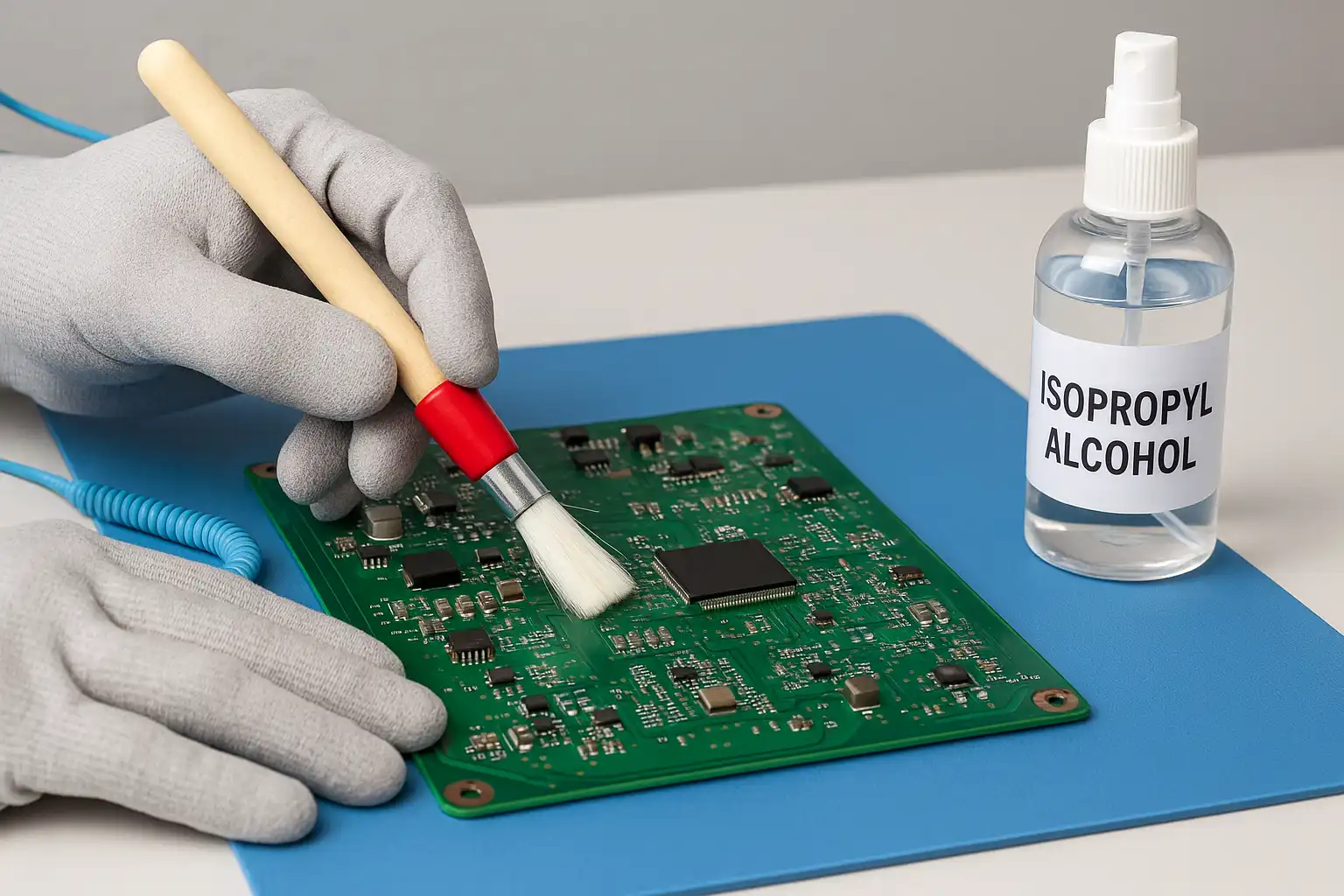
Step 5: Clean the Board
After repairs, clean the PCB with isopropyl alcohol and a brush to remove flux residue or debris. This prevents corrosion and ensures clear visibility for future inspections. Dry the board thoroughly before testing.
Step 6: Test the Circuit
Power on the circuit and monitor its behavior. Check if the original symptoms persist. If issues remain, repeat the inspection and testing process, focusing on areas not previously addressed. Use a schematic diagram if available to trace signal paths and identify faults.
Preventive Best Practices
- Use a soldering iron with adjustable temperature control to avoid overheating.
- Secure components with temporary adhesive or by bending leads slightly before soldering.
- Work on a stable, well-lit surface to ensure precision during assembly.
- Store PCBs and components in anti-static packaging to prevent electrostatic damage.
Troubleshooting Case Study: Fixing a Power Supply Circuit
Consider a scenario where a hobbyist builds a simple power supply circuit using THT components, including a transformer, diodes, and capacitors. After assembly, the circuit fails to output the expected voltage. Following the steps outlined, the hobbyist begins with a visual inspection and notices a dull solder joint on one diode lead. Using a multimeter, continuity is tested and found lacking at that joint.
The hobbyist reflows the joint with fresh solder, ensuring proper heat application. After cleaning the board, the circuit is powered on again. The output voltage now matches the design specification, confirming the solder joint as the issue. This example highlights how systematic THT circuit troubleshooting can resolve common faults without replacing components unnecessarily.
Conclusion
Troubleshooting THT assembly issues is a valuable skill for electronic hobbyists aiming to build reliable circuits. By understanding the causes of common problems like poor solder joints and component misalignment, enthusiasts can apply targeted solutions to fix THT issues. Visual inspection, continuity testing, and proper soldering techniques form the backbone of effective electronic repair. With practice and attention to detail, hobbyists can overcome assembly challenges and achieve consistent results in their projects. Following best practices ensures long-term circuit reliability and enhances the learning experience in electronics.
FAQs
Q1: What are the most common causes of THT circuit troubleshooting problems?
A1: Common causes include poor solder joints due to insufficient heat or contamination, component misalignment during assembly, and thermal stress from excessive soldering temperatures. Mechanical stress on leads can also cause failures. Identifying these issues through visual inspection and testing with a multimeter helps in effective troubleshooting for hobbyists.
Q2: How can I fix THT issues like cold solder joints at home?
A2: To fix cold solder joints, reheat the joint with a soldering iron at the appropriate temperature and apply fresh solder. Ensure the joint looks shiny and smooth after reflowing. Clean the area with isopropyl alcohol to remove residue. This simple electronic repair technique works well for most THT assembly faults.
Q3: What tools are essential for fixing THT issues in circuits?
A3: Essential tools include a soldering iron with temperature control, a multimeter for continuity testing, a desoldering pump for removing old solder, and a magnifying glass for inspection. A brush and isopropyl alcohol are also useful for cleaning. These tools support effective THT circuit troubleshooting for hobbyists.
Q4: How do I prevent damage during electronic repair of THT boards?
A4: Prevent damage by using the correct soldering temperature and limiting heat exposure to components. Secure components before soldering to avoid misalignment. Work on a stable surface and use anti-static protection. Careful handling during THT circuit troubleshooting reduces the risk of further issues.
References
IPC-A-600K — Acceptability of Printed Boards. IPC, 2020.
IPC J-STD-001H — Requirements for Soldered Electrical and Electronic Assemblies. IPC, 2021.


