Introduction
Electronic hobbyists frequently encounter the frustration of a non-functional circuit board, often traced back to a blown fuse. These small components act as critical safeguards, interrupting excessive current to prevent damage to sensitive electronics. Understanding how to troubleshoot blown fuses on PCBs can save time, reduce costs, and restore projects quickly. This guide provides a practical, step-by-step approach tailored for hobbyists, covering symptoms, testing, analysis, and replacement. By following these methods, you can diagnose issues efficiently and get back to prototyping. Whether working on audio amplifiers, power supplies, or custom controllers, mastering PCB fuse troubleshooting is an essential skill.
What Are PCB Fuses and Why Do They Matter?
PCB fuses are protective devices mounted directly on printed circuit boards to monitor and limit current flow. They come in various types, including surface-mount device (SMD) fuses, axial through-hole fuses, and resettable polymeric positive temperature coefficient (PPTC) fuses. When current exceeds the rated value, the fuse element melts or opens, breaking the circuit and protecting downstream components from overload. For hobbyists, fuses matter because they prevent catastrophic failures in experiments with motors, LEDs, or microcontrollers. Ignoring a blown fuse can lead to repeated damage, wasted parts, and safety risks like overheating. Proper fuse selection and maintenance align with assembly standards like IPC-A-610H, which outlines acceptability criteria for electronic assemblies.
Fuses on PCBs differ from household ones by their compact size and integration into high-density layouts. SMD fuses, common in modern designs, offer low profiles but require precise handling. PPTC fuses automatically reset after cooling, ideal for transient faults in battery-powered gadgets. Despite their simplicity, fuse failures disrupt entire systems, halting power delivery. Hobbyists benefit from recognizing their role early to avoid trial-and-error repairs.
Common Blown Fuse Symptoms on PCBs
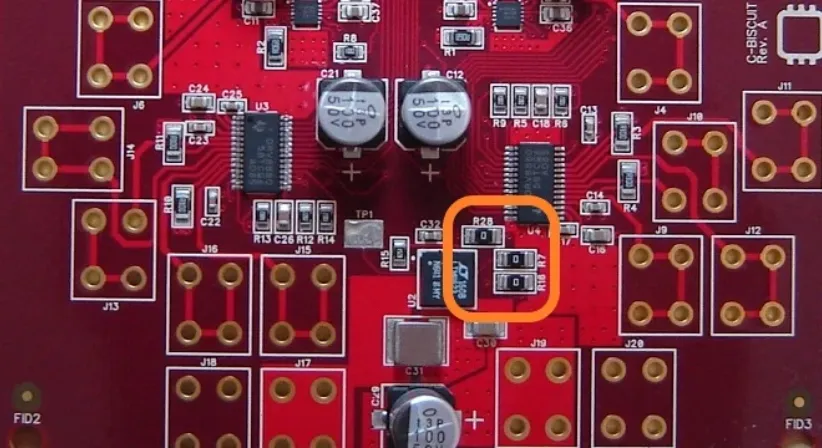
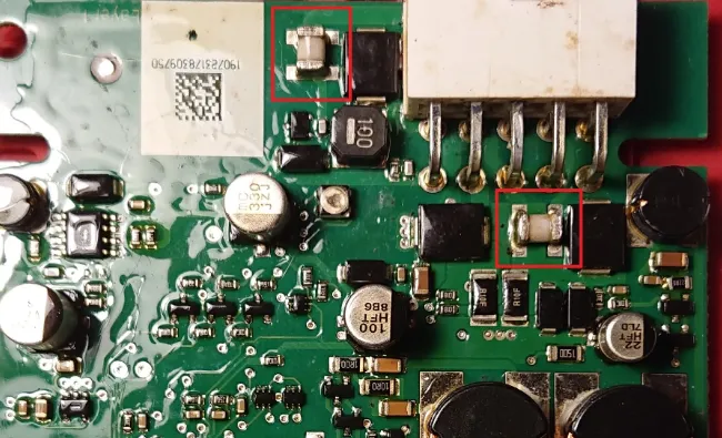
Spotting blown fuse symptoms early prevents unnecessary probing into complex circuitry. The most obvious sign is total loss of power to the board or affected section, with no LED indicators or output signals. A burnt smell or visible charring around the fuse area often accompanies failure, indicating thermal runaway. Discoloration, such as blackened epoxy on SMD fuses or a snapped wire in glass types, provides clear visual clues. In some cases, the board may power up partially, with erratic behavior like flickering displays pointing to intermittent fuse issues.
Other symptoms include unusual heat from nearby components or repeated tripping of external power supplies. Hobbyists might notice these during initial power-on tests or after connecting peripherals. Auditory cues, like popping sounds during operation, signal impending or recent fuse blows. Always power down immediately upon detecting these signs to avoid further damage. Documenting symptoms helps in fuse failure analysis later.
Causes of Fuse Failure: In-Depth Analysis
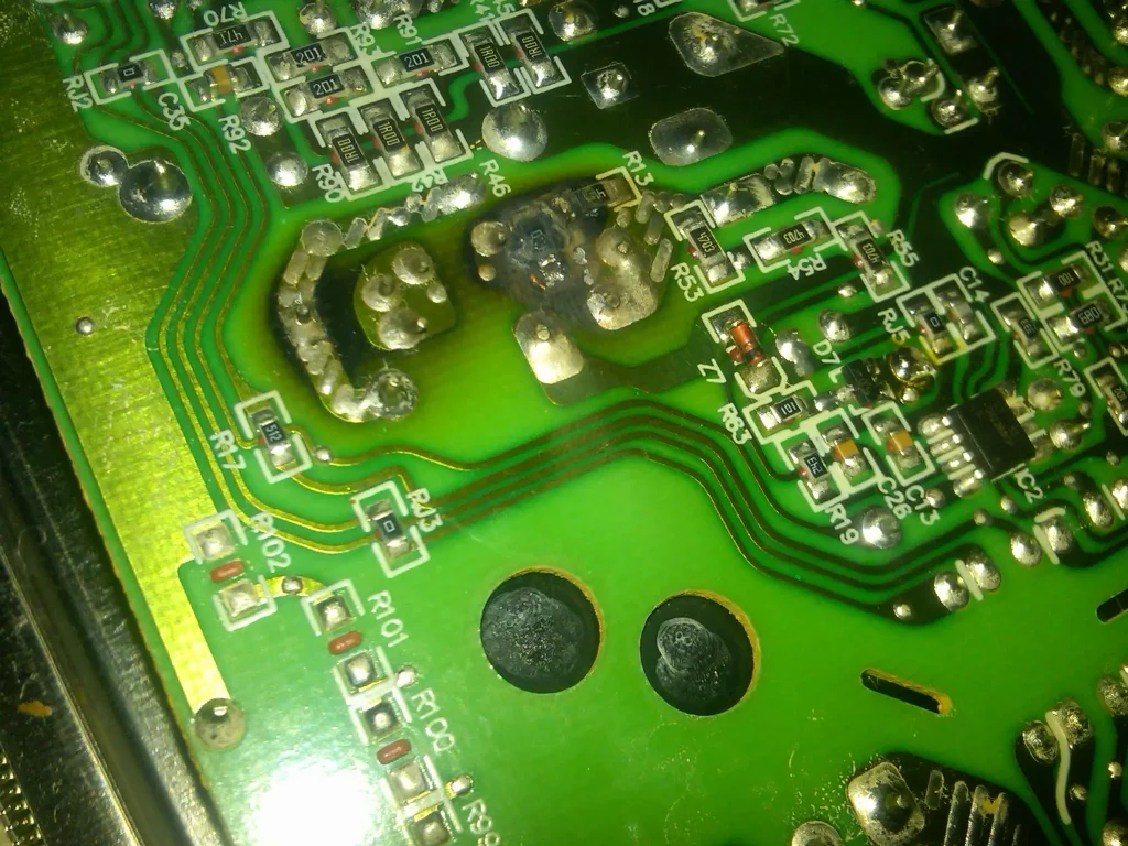
Fuse failure analysis reveals that overcurrent from short circuits tops the list of causes. A solder bridge, faulty capacitor, or reversed polarity can draw excessive amps, melting the fuse element rapidly. Power surges from unstable supplies or electrostatic discharge (ESD) events overwhelm ratings, especially in unprotected hobby setups. Manufacturing defects, like voids in solder joints per IPC-A-610H criteria, contribute indirectly by creating high-resistance paths that generate heat.
Component aging plays a role too, with electrolytic capacitors leaking and pulling surplus current over time. Incorrect fuse ratings, such as using a 1A fuse for a 2A load, guarantee premature failure. Environmental factors like humidity cause corrosion on pads, leading to arcing. Inadequate PCB trace widths exacerbate issues by dropping voltage and heating up. Thorough analysis involves checking upstream and downstream circuits post-replacement.
Mechanical stress from mishandling vibrates fuses loose, mimicking open circuits. Hobbyists experimenting with high-power mods often overlook these. Tracing root causes prevents recurrence.
Tools and Safety for PCB Fuse Troubleshooting
Effective PCB fuse troubleshooting starts with basic tools: a digital multimeter for continuity and voltage checks, soldering iron with fine tips, desoldering wick or pump, and magnifying glass or microscope. Anti-static wrist straps protect sensitive parts, while isopropyl alcohol cleans residues. Safety goggles and well-ventilated workspaces handle fumes from desoldering. Always discharge capacitors before probing to avoid shocks.
Power off and unplug the board first, verifying no residual voltage with the multimeter. Label components to track positions. Isopropyl alcohol and flux aid in clean removals. These preparations ensure safe, precise work.
Step-by-Step Guide to Fuse Testing Methods
Begin fuse testing methods with a visual inspection under good lighting. Look for cracks, bulges, or melt marks on the fuse body. Magnify SMD types for end-cap separation. Per J-STD-001H soldering standards, check pad integrity around the fuse.
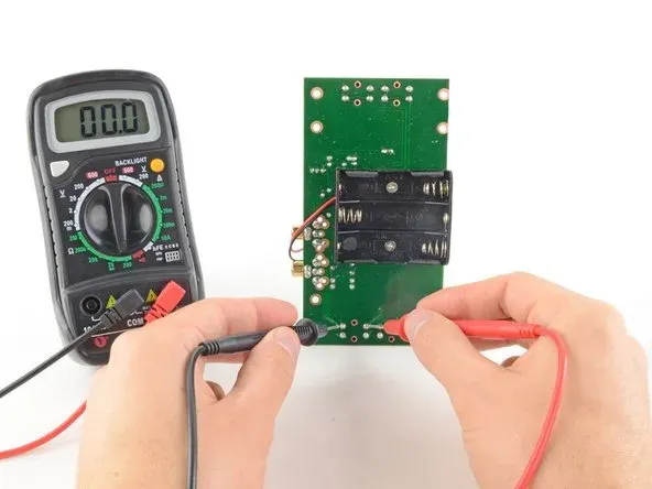
Next, perform an in-circuit continuity test. Set the multimeter to ohms or diode mode, probing fuse leads. Infinite resistance or no beep indicates an open fuse. Voltage drop across the fuse under power should be near zero; higher values suggest partial failure.
For accuracy, desolder the fuse using wick and iron at 350°C max. Out-of-circuit, confirm continuity; good fuses show low ohms. Test for shorts elsewhere by measuring resistance from power rails to ground. Re-inspect pads post-removal.
If the fuse passes but issues persist, analyze upstream: measure input voltage stability and scan for shorts with the meter in low-ohms mode. Thermal imaging, if available, spots hot spots.
Replacing a PCB Fuse: Best Practices
Replacing PCB fuse demands matching exact specs: current rating, voltage, and type from markings or schematics. Source generics with identical footprint. Clean pads thoroughly with alcohol after desoldering.
Apply flux, tin pads lightly, and position the new fuse. Solder symmetrically, avoiding bridges or cold joints per J-STD-001H guidelines. Inspect fillets and wetting for acceptability. Trim excess leads on through-hole types.
Power up cautiously with a current-limited supply, monitoring for stability. Test functionality across the board. If it blows again, revisit failure analysis.
Preventing Future Fuse Blows
Select fuses with 25-50% headroom over expected max current. Add transient voltage suppressors for surge protection. Use proper trace widths calculated for current density. Fuse resettable types for non-critical paths.
Routine inspections catch early wear. ESD-safe handling preserves integrity. These practices extend board life.
Common Troubleshooting Scenarios for Hobbyists
In a motor driver project, repeated blows often stem from stalled motors drawing locked-rotor current. Check motor wiring and add snubbers. Audio amps fail from speaker shorts; verify output stages.
Power supply mods blow from reversed diodes; polarity test everything. These scenarios highlight systematic checks.
Conclusion
Troubleshooting blown fuses on PCBs empowers hobbyists to diagnose and repair efficiently. From recognizing blown fuse symptoms to advanced fuse testing methods and precise replacement, this guide covers essentials. Adhering to standards like IPC-A-610H ensures reliable outcomes. Prevent issues through proper design and handling. Apply these steps to revive projects confidently, turning setbacks into learning opportunities.
FAQs
Q1: What are the most common blown fuse symptoms on a PCB?
A1: Blown fuse symptoms include no board power, burnt odors, visible charring, or discoloration on the fuse. Partial power with flickering may occur in marginal cases. Always inspect visually first during PCB fuse troubleshooting to confirm. This quick check saves time before deeper tests.
Q2: How do you perform fuse testing methods without desoldering?
A2: Use a multimeter for in-circuit continuity; infinite resistance signals failure. Check voltage drop under power; it should be minimal. Probe carefully to avoid shorts. These non-invasive fuse testing methods suit quick diagnostics for hobbyists.
Q3: What steps are involved in fuse failure analysis after replacement?
A3: Examine root causes like shorts or surges post-replacement. Measure circuit currents and inspect components. Recheck with limited power. Fuse failure analysis prevents repeats, ensuring robust repairs.
Q4: When replacing PCB fuse, what precautions matter most?
A4: Match ratings exactly, clean pads, and solder per standards. Test incrementally. Replacing PCB fuse incorrectly risks recurrence. Use flux for clean joints.
References
IPC-A-610H — Acceptability of Electronic Assemblies. IPC, 2019
J-STD-001H — Requirements for Soldered Electrical and Electronic Assemblies. IPC, 2018
IPC-7711/7721C — Rework, Modification and Repair of Electronic Assemblies. IPC, 2020