Introduction
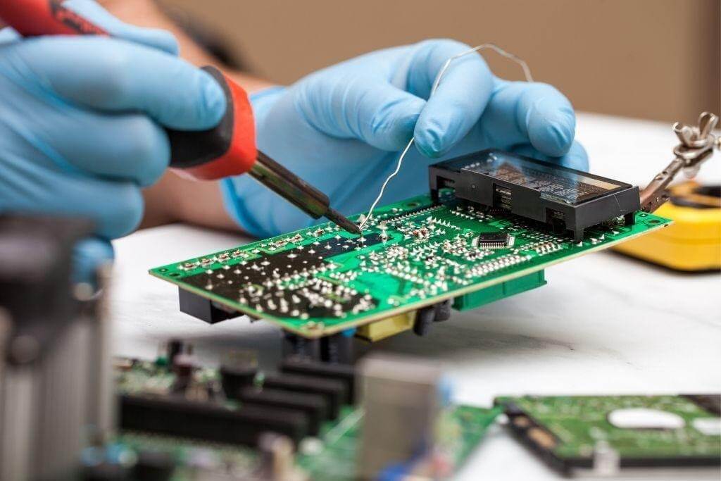
Manual soldering stations remain essential tools for electric engineers working on PCB assembly and repair tasks. These stations provide precise control over temperature and power delivery, making them ideal for prototyping, rework, and small-scale production. However, like any precision equipment, they can encounter issues that disrupt workflow and compromise joint quality. Problems such as a soldering iron not heating up, soldering station temperature fluctuations, or soldering tip oxidation problems often arise from everyday use. This guide offers practical troubleshooting steps tailored for engineers, drawing on established principles to restore performance quickly. By addressing these issues systematically, you can minimize downtime and ensure reliable solder joints that meet assembly standards.
Understanding Manual Soldering Stations and Why Troubleshooting Matters
A manual soldering station typically consists of a control unit, heating element, thermocouple or sensor for temperature feedback, and interchangeable tips designed for various joint sizes. Electric engineers rely on these stations for their adjustability, allowing settings from 200°C to 480°C depending on the alloy and component sensitivity. Troubleshooting matters because unreliable stations lead to defects like cold solder joints, which weaken electrical connections and fail reliability tests. In high-stakes applications, such as aerospace or medical electronics, even minor fluctuations can cascade into assembly failures. Proper maintenance extends station life and aligns with industry standards like J-STD-001, which specifies requirements for soldered electrical assemblies. Mastering these skills ensures consistent quality in PCB rework and prototyping.
Common Causes of Soldering Iron Not Heating Up
One of the most frustrating issues is when the soldering iron not heating up, halting production entirely. This problem often stems from a failed heating element, where internal coils break due to thermal cycling over time. Power supply interruptions, such as loose connections in the cord or a tripped internal fuse, also prevent current flow to the element. Engineers should first verify the outlet and cable integrity using a multimeter for continuity. Sensor failures can mimic this by blocking power until temperature feedback confirms safe operation. Understanding these root causes prevents misdiagnosis and repeated disassembly.
Mechanisms Behind Soldering Station Temperature Fluctuations
Soldering station temperature fluctuations disrupt joint formation by causing inconsistent wetting of solder to pads and leads. These variations typically result from a degraded thermocouple or thermistor, which drifts in accuracy after prolonged exposure to high heat. Control circuit instability, including capacitor aging or feedback loop errors, amplifies overshoots and undershoots during rapid adjustments. Ambient conditions like drafts or high humidity can influence sensor readings, leading to erratic behavior. In precision work, even 10-20°C swings affect intermetallic compound formation, risking brittle joints. Regular calibration against reference points helps quantify these drifts early.
Soldering Tip Oxidation Problems and Their Impact
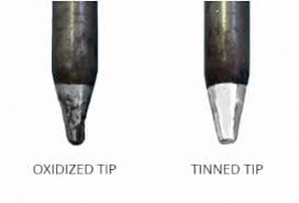
Soldering tip oxidation problems occur when the iron plating on tips corrodes, forming an insulating oxide layer that impairs heat transfer. Exposure to air at elevated temperatures accelerates this, especially if tips rest idle without flux or solder coverage. Engineers notice reduced thermal conductivity, manifesting as longer dwell times and poor solder flow. Contaminated flux residues exacerbate oxidation by trapping moisture and acids on the surface. This issue directly contributes to troubleshooting cold solder joints, as oxidized tips fail to maintain the necessary clean, tinned interface. Preventive habits like immediate tinning after use mitigate long-term degradation.
Root Causes of Cold Solder Joints in Manual Soldering
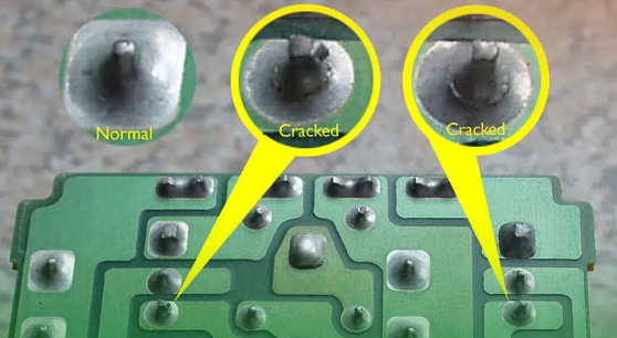
Troubleshooting cold solder joints requires identifying insufficient reflow, where solder solidifies before fully wetting surfaces. Low temperature settings or inadequate iron contact time prevent proper alloy melting and flux activation. Component movement during cooling disturbs the joint, creating a dull, grainy appearance rather than the desired shiny fillet. Insufficient flux or contaminated pads hinder capillary action, leaving voids or dewetting. These defects violate acceptability criteria in IPC-A-610, which defines class-specific joint profiles for electronic assemblies. Engineers must correlate station performance with visual and mechanical inspections to pinpoint station-related faults.
The Role of Manual Soldering Station Maintenance in Prevention
Manual soldering station maintenance forms the foundation for avoiding most operational issues. Dust accumulation in vents blocks airflow, causing overheating and element stress. Infrequent tip cleaning with brass wool or activated sponges removes oxides but must avoid abrasive damage to plating. Firmware or analog controls benefit from periodic zeroing against known temperatures, ensuring setpoint accuracy. Logging usage hours helps predict component wear, scheduling replacements proactively. Adhering to these routines aligns with reliability practices in J-STD-001, reducing defect rates in PCB assembly.
Practical Troubleshooting Steps for Heating Failures
Start troubleshooting a soldering iron not heating up by isolating power issues: test the station on multiple outlets and inspect the cord for frays or breaks. Use a multimeter to check voltage at the iron connector, confirming delivery matches specifications. If power reaches the unit, suspect the heating element; resistance should read 10-50 ohms depending on wattage, with open circuits indicating failure. Replace fuses or reset thermal cutoffs if equipped. For sensor faults, bypass checks require caution to avoid warranty voids. Document findings for pattern analysis across multiple stations.
Stabilizing Soldering Station Temperature Fluctuations
To address soldering station temperature fluctuations, perform a stability test by monitoring output over 30 minutes at a fixed setpoint like 350°C using an external thermocouple. Deviations beyond ±5°C signal sensor drift; recalibrate per manufacturer trims or replace the thermocouple. Clean control board contacts and capacitors to eliminate noise in the feedback loop. Insulate the iron barrel to reduce ambient heat loss, stabilizing readings. Verify ground integrity to prevent electrical interference. These steps restore precision for sensitive lead-free soldering.
Resolving Soldering Tip Oxidation Problems Effectively
Combat soldering tip oxidation problems by selecting tips with thick iron plating and storing them tinned in a protective rack. Activate new tips by generously applying flux and fresh solder at 350°C until bright and shiny. During use, wipe on a damp sponge every few joints, followed by tinning to self-protect the surface. Avoid high-idle temperatures above 400°C, which accelerate oxide growth. For severe cases, file lightly with fine emery before re-tinning, restoring thermal mass. Consistent habits extend tip life beyond thousands of cycles.
Step-by-Step Guide to Troubleshooting Cold Solder Joints
Troubleshooting cold solder joints begins with visual inspection under 10x magnification for cracks or incomplete fillets. Rework suspect joints by cleaning with isopropyl alcohol and no-clean flux, then reapply heat with good tip contact for 3-5 seconds. Verify station temperature with a pyrometer on a test pad to rule out low heat. Adjust dwell time and angle for optimal wetting, ensuring 60/40 or lead-free alloys flow smoothly. Test continuity and pull strength post-repair. Integrate these into a station checklist for ongoing quality control.
Best Practices for Long-Term Manual Soldering Station Maintenance
Implement a weekly manual soldering station maintenance routine: inspect cords, clean vents, and test all temperature setpoints. Rotate tips to even wear and track replacement intervals based on joint volume. Use only compatible solder and flux to prevent corrosive buildup. Store stations in low-humidity environments to protect electronics. Train teams on error logging, correlating issues with usage patterns. These practices not only prevent downtime but enhance compliance with IPC-A-610 joint criteria.
Real-World Insights from PCB Assembly Troubleshooting
In a typical rework scenario, an engineer faced persistent soldering station temperature fluctuations during high-volume QFN attach. Root cause traced to a drifting thermistor, confirmed by logging data over shifts. Swapping the sensor and recalibrating resolved swings, dropping defect rates significantly. Another case involved soldering tip oxidation problems from improper storage, fixed by adopting tinned racks and flux dipping. Troubleshooting cold solder joints often revealed combined issues like low flux and marginal heat, underscoring holistic station checks. These examples highlight how methodical diagnostics prevent recurrence in production.
Conclusion
Mastering troubleshooting for manual soldering stations empowers electric engineers to maintain peak performance in PCB assembly. Key issues like soldering iron not heating up, temperature fluctuations, tip oxidation, and cold joints share preventable causes rooted in wear and habits. Systematic checks, from power verification to tip care, restore reliability swiftly. Integrating manual soldering station maintenance into workflows ensures durable joints meeting J-STD-001 and IPC-A-610 standards. By applying these practical steps, you minimize defects, extend equipment life, and support efficient prototyping and repair.
FAQs
Q1: What should I do if my soldering iron not heating up during a critical assembly?
A1: First, check power supply by testing outlets and cord continuity with a multimeter. Inspect for blown fuses or loose connectors at the iron base. Measure heating element resistance; infinite readings confirm failure needing replacement. Avoid disassembly without ESD protection to prevent static damage. This quick sequence often resolves the issue in under 10 minutes, restoring workflow.
Q2: How can I fix soldering station temperature fluctuations for precise rework?
A2: Monitor with an external thermocouple at 350°C for stability over 20 minutes. Clean sensor contacts and recalibrate feedback trims if drifts exceed ±10°C. Insulate the iron to counter ambient effects and verify grounding. Replace aged thermocouples promptly. These steps ensure consistent heat for lead-free joints, aligning with assembly standards.
Q3: What causes soldering tip oxidation problems and how to prevent them?
A3: Oxidation forms from air exposure at heat, insulating the tip surface. Prevent by tinning immediately after use and wiping with flux-activated sponges. Store in protective holders at room temperature. Select quality-plated tips and avoid prolonged idling above 300°C. Regular maintenance keeps heat transfer optimal, reducing joint defects.
Q4: Why do cold solder joints occur and what's the best troubleshooting approach?
A4: Insufficient heat or movement during solidification creates grainy, weak connections. Troubleshoot by verifying station temperature on test pads and ensuring 4-second dwell with flux. Inspect for pad contamination and rework with fresh alloy. Check tip condition to rule out oxidation. This methodical process yields reliable fillets per IPC criteria.
References
J-STD-001G — Requirements for Soldered Electrical and Electronic Assemblies. IPC, 2017
IPC-A-610H — Acceptability of Electronic Assemblies. IPC, 2019


