What Are SMT Assembly Defects and Why Do They Impact Production?
Surface Mount Technology (SMT) assembly defects refer to imperfections or errors that emerge during the process of mounting electronic components onto a printed circuit board (PCB). These flaws can critically undermine the functionality, dependability, and expected lifespan of the final electronic product. For engineers, a thorough understanding and proactive resolution of these issues are paramount. Even a seemingly small defect rate, for example, 1%, can translate into thousands of faulty units in large-scale manufacturing, leading to substantial financial losses and reputational damage.
The Criticality of Defect Management
Common SMT assembly problems encompass issues such as incorrect soldering, misaligned components, and insufficient solder paste application. These often originate from fundamental design flaws, equipment malfunctions, or human error in the production line. By becoming proficient in SMT assembly defect identification and prevention, engineers can significantly reduce costly rework operations and enhance overall production yield rates, thereby streamlining the manufacturing process.
What Are the Most Common SMT Assembly Problems?
Before delving into specific diagnostic and repair strategies, it’s helpful to survey the most frequently encountered issues in SMT assembly. Early recognition of these problems is the foundational step toward effective resolution.
Typical SMT Manufacturing Flaws
● Tombstoning: This occurs when a component lifts upright on one end, visually resembling a tombstone, typically due to uneven solder wetting.
● Solder Bridges: These are unintended electrical connections formed by excess solder linking adjacent pads or component leads.
● Component Misalignment: Components are incorrectly positioned on the PCB pads, which can lead to poor or absent electrical connections.
● Insufficient Solder: An inadequate volume of solder paste applied results in weak, fragile, or incomplete solder joints.
● Cold Solder Joints: These appear dull, granular, or cracked rather than shiny and smooth, indicating a poor metallurgical bond that can cause intermittent electrical failures.
Each of these defects has distinct underlying causes and necessitates specific preventive measures and rework procedures.
How Do You Identify SMT Assembly Defects Early?
Detecting SMT assembly defects promptly in the production cycle is crucial for conserving both time and resources. Visual inspection, Automated Optical Inspection (AOI), and X-ray inspection are among the most effective methods for pinpointing these issues.
Effective Defect Detection Methods
● Tombstoning: Look for components visibly lifted on one side. This defect is often discernible through naked-eye inspection or with the aid of AOI systems.
● Solder Bridges: Scrutinize for shiny, unwanted solder connections between adjacent pads or pins, particularly common with fine-pitch components.
● Component Misalignment: Verify placement accuracy using AOI systems or through careful manual checks. Misaligned components will not properly engage their designated pads.
● Insufficient Solder: Inspect joints for an incomplete appearance or noticeable gaps. X-ray inspection is particularly effective for revealing hidden issues beneath components.
● Cold Solder Joints: These joints typically lack the characteristic shiny, smooth appearance of a good joint, often looking dull or fractured. They are prone to failure under mechanical stress or vibration.
Utilizing a blend of inspection techniques ensures a higher rate of defect detection. For example, AOI systems can achieve up to a 95% detection rate for visible flaws, while X-ray systems are indispensable for identifying concealed solder joint problems, especially under complex packages like BGAs.
What Are the Root Causes of SMT Assembly Defects?
To effectively prevent defects, a deep understanding of their origins is essential. Here are the primary factors contributing to common SMT assembly problems.
1. Design-Related Issues
Poor PCB layout or inadequate pad design can directly contribute to issues like tombstoning or component misalignment. For instance, if component pads are disproportionately small, solder might not wet evenly across both terminals, causing one end of the component to lift. It’s crucial to ensure pad dimensions are optimized to component specifications, typically aiming for a pad width 1.2 to 1.5 times the component lead width for superior soldering.
2. Solder Paste Application Problems
Inconsistent or insufficient application of solder paste frequently leads to weak joints or areas with insufficient solder. Issues such as stencil misalignment or clogged apertures can reduce the deposited paste volume by as much as 30%, resulting in defective solder joints. Regular cleaning of SMT stencil and verification of paste volume using automated inspection systems are vital preventive measures.
3. Component Placement Errors
Inaccurate placement by automated pick-and-place machines can result in misalignment. Factors such as calibration drift in the machinery or incorrect feeder setup can cause placement inaccuracies as subtle as 0.1 mm, which is enough to compromise fine-pitch components. Implementing routine calibration checks for placement equipment is therefore indispensable.
4. Reflow Soldering Process Faults
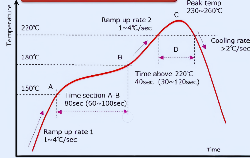
Incorrectly configured reflow profiles are a common cause of cold solder joints or tombstoning. If the preheat stage is too brief, components may not reach the necessary activation temperature (typically 150-180°C) before the main reflow phase, leading to uneven solder wetting. Continuous monitoring and adjustment of reflow profiles based on specific board and component requirements are critical.
5. Environmental Conditions
Fluctuations in humidity and temperature within the assembly environment can adversely affect solder paste performance. High humidity levels (exceeding 60%) can cause solder paste to absorb moisture, diminishing its efficacy and leading to defects. Maintaining tightly controlled environmental conditions is crucial to prevent such issues.
What Are the Best Prevention Strategies for SMT Assembly Defects?
Preventing SMT assembly defects is consistently more cost-effective than undertaking rework. Engineers can implement several actionable strategies to minimize common problems.
Key Prevention Techniques for Engineers
● Optimize PCB Design: Start with a design that inherently supports reliable assembly. Integrate Design for Manufacturing (DFM) guidelines to ensure that pad sizes, spacing, and thermal balance are appropriate. For instance, creating identically sized pads on both ends of a component can prevent tombstoning by encouraging uniform solder wetting.
● Utilize High-Quality Materials: Invest in superior solder paste and reputable components. Substandard solder paste can exhibit inconsistent viscosity, leading to uneven application. Always verify paste specifications for particle size (typically Type 3 or 4 for fine-pitch applications) and recommended storage conditions (generally 2-10°C).
● Regular Equipment Calibration: Ensure that all critical equipment, including pick-and-place machines, stencil printers, and reflow ovens, undergoes routine calibration. Well-maintained machinery can achieve placement accuracies of ±0.025 mm, significantly reducing the risk of component misalignment.
● Implement Robust Process Controls: Employ Statistical Process Control (SPC) to continuously monitor key variables such as solder paste volume and reflow temperatures. Establish precise control limits—for example, maintaining peak reflow temperatures between 235-250°C for lead-free solder—to identify and correct deviations swiftly.
● Invest in Personnel Training: Human error contributes to a substantial portion of manufacturing defects. Provide comprehensive training on proper handling techniques, equipment operation, and effective defect identification. A well-trained team can realistically reduce error rates by up to 20%.
How Do You Rework SMT Assembly Defects Effectively?
Despite the most rigorous prevention strategies, defects can still occur. Possessing effective SMT assembly rework techniques is essential for minimizing losses and maintaining product quality.
Efficient Rework Procedures for Common Defects
● Reworking Tombstoning: Use a hot air rework station to carefully reflow the affected component. Apply flux to the pads, then heat the area to 240-260°C for lead-free solder, ensuring the solder wets evenly. If necessary, gently reposition the component using fine tweezers. Avoid applying excessive heat to prevent damage to adjacent components or the PCB itself.
● Removing Solder Bridges: Employ a solder wick or desoldering braid with a soldering iron set to 300-350°C to carefully absorb the excess solder. Applying flux to the bridge initially will help facilitate the solder flow into the wick. Afterward, clean the area thoroughly with isopropyl alcohol to remove any flux residue.
● Correcting Misaligned Components: For minor misalignments, simply reflow the component using a hot air station and gently reposition it into place. In more severe cases, it is best to completely remove the component using appropriate desoldering tools, clean the pads, and then re-place it with fresh solder paste, ensuring precise alignment.
● Fixing Insufficient Solder: Add a small amount of fresh solder to the joint using a fine-tip soldering iron. Apply flux beforehand to ensure proper adhesion and flow. Be cautious not to over-apply, as excessive solder can inadvertently create new solder bridges.
● Addressing Cold Solder Joints: Reflow the faulty joint with a soldering iron or a hot air tool, ensuring the temperature reaches and sustains the melting point of the solder (around 217°C for lead-free alloys). Add flux to enhance wetting and then visually inspect the joint for a characteristic shiny, smooth finish.
What Advanced Tools Enhance SMT Troubleshooting?
Modern tools and technologies can significantly improve an engineer’s capability to identify and rectify SMT assembly defects. Automated Optical Inspection (AOI) systems, for example, can rapidly scan circuit boards at speeds up to 100 cm² per second, detecting visible defects with up to 99% accuracy. X-ray inspection is invaluable for uncovering hidden solder joint issues, particularly beneath complex BGA (Ball Grid Array) components, where defects are entirely invisible to the naked eye.
Furthermore, thermal imaging cameras can detect undesirable hot spots or uneven heating during the reflow process, providing critical data for optimizing reflow profiles. Strategic investment in such advanced tools can reduce defect rates by as much as 30% in high-volume manufacturing environments, leading to substantial savings and improved product quality.
Case Study: Drastically Reducing Defect Rates in Production
Consider a real-world example where a manufacturer was grappling with a persistent 5% defect rate attributed to tombstoning within a production batch of 10,000 units. Through a meticulous analysis of their reflow profile, engineers discovered that the preheat stage was critically insufficient, leading to uneven thermal distribution across components. By precisely adjusting the profile to incorporate an extended 120-second preheat phase at 150°C, the defect rate plummeted to under 1%. This seemingly simple process modification resulted in savings of thousands of dollars in rework PCB broad cost and significantly improved product delivery timelines.
This case vividly illustrates the profound importance of data-driven troubleshooting and continuous process optimization within SMT assembly operations.
Conclusion: Achieving Reliable SMT Assembly
SMT assembly defects, while a substantial challenge for engineers, are entirely manageable with the right knowledge, tools, and strategic approach. By diligently focusing on SMT assembly defect identification, comprehending their underlying causes, implementing proactive prevention strategies, and mastering efficient rework techniques, you can achieve higher production yields and significantly improve product reliability.
Begin by integrating the best practices and insights outlined in this guide into your daily workflow. Consistently inspect and refine your processes, ensure your team is thoroughly trained, and leverage advanced inspection tools to anticipate and mitigate common SMT assembly problems. Through a proactive and informed approach, you will minimize defects and guarantee that your PCBs consistently adhere to the most stringent quality standards.