Introduction
In PCB design, connecting traces without adding resistance often requires careful choices between zero-ohm resistors and jumpers. These components serve similar purposes as low-impedance links but differ in assembly compatibility, current handling, and flexibility. Engineers frequently debate zero ohm resistor vs jumper usage, especially in space-constrained or high-volume production layouts. Understanding their roles ensures optimal signal integrity, manufacturability, and reliability. This article explores their definitions, applications, and PCB design considerations to guide informed decisions.
What Is a Zero-Ohm Resistor?
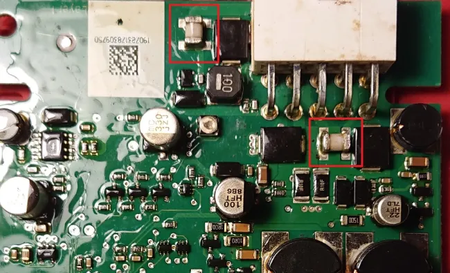
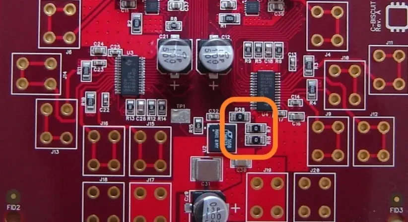
A zero-ohm resistor appears as a standard resistor but carries a nominal resistance of zero ohms, functioning as a conductive bridge between two points. Its actual resistance measures a few milliohms due to the metal link inside, yet it behaves like a short circuit for DC signals. Packaged in common sizes like 0402, 0603, or 0805, it integrates seamlessly into surface-mount assembly lines. The component includes a power rating, similar to regular resistors, which limits the maximum current based on thermal dissipation. Engineers value it for automated pick-and-place processes, as machines treat it like any resistor.
Zero-ohm resistors provide options for circuit configuration by selectively populating or removing them during assembly. They also serve as test points or fuses in prototypes, allowing easy disconnection for troubleshooting. In multi-layer boards, they bridge routing gaps where traces cannot cross without vias. Adhering to land pattern standards like IPC-7351 ensures proper soldering and reliability.
What Is a Jumper in PCB Design?
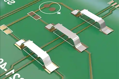
A jumper in PCB context refers to a short conductive element that links two adjacent pads or traces, typically without any resistor-like packaging. SMT jumpers consist of preformed metal bars or blobs designed for surface-mount reflow soldering, offering a compact alternative for simple connections. Wire jumpers or solder bridges suit hand assembly or single-sided boards, where manual bridging occurs post-etching. These lack formal power ratings but handle currents based on their cross-section and pad size. Jumpers excel in cost-sensitive designs requiring minimal components.
Jumper applications often involve bypassing obstacles in trace routing, especially on two-layer boards with limited layers. They enable quick modifications during prototyping without altering the base layout. In high-current paths, wider SMT jumpers provide better thermal margins than narrow resistor bodies. Proper pad spacing prevents shorts during reflow, aligning with assembly guidelines.
Key Differences: Zero-Ohm Resistor vs Jumper
Zero-ohm resistors and jumpers both create low-resistance paths, but their form factors dictate distinct advantages. A zero-ohm resistor uses a resistor body with end caps, supporting standard footprints and pick-and-place handling, while a jumper relies on bare metal shapes like bars or bridges. This makes zero-ohm resistors preferable for high-volume SMT lines, as they avoid custom feeder setups for jumpers. Jumpers, however, occupy less board space and cost less per unit in bulk.
Power handling represents another divergence. Zero-ohm resistors carry explicit power ratings, guiding selection for currents where I-squared-R heating applies despite low R. Jumpers depend on empirical limits from material and geometry, often exceeding resistor capacities in thick variants. Removal ease favors zero-ohm resistors, as soldering tools desolder them cleanly without scraping solder bridges. Signal integrity at high frequencies may vary, with zero-ohm resistors introducing slight inductance from their length.
In terms of PCB jumper routing, jumpers integrate directly into traces for seamless flow, whereas zero-ohm resistors add a discrete component step. Both must follow design rules for clearance and creepage to avoid failures.
Zero-Ohm Resistor Applications
Zero ohm resistor applications span configuration, protection, and routing in diverse circuits. They act as optional links in power distribution, populated for parallel paths or omitted for series isolation. In RF prototypes, they isolate sections for tuning, minimizing parasitic effects during characterization. Current sharing between supplies uses multiple zero-ohm resistors to balance loads evenly across traces.
Debugging benefits from their removability, allowing engineers to break loops or inject signals without cutting traces. As fuses, they protect sensitive ICs by failing open under overload, based on their power rating. In dense layouts, they jump signals over ground planes, preserving layer stackup integrity. Compliance with soldering standards like J-STD-001 ensures robust joints in these roles.
Jumper Applications
Jumper applications focus on simplicity and economy in PCB jumper routing scenarios. On single-layer boards, they cross traces that cannot share layers, enabling compact designs without vias. SMT jumpers suit high-speed signals needing minimal inductance, as their short length reduces parasitics compared to longer resistor spans. In power sections, they handle bulk currents where resistor bodies might overheat.
Prototyping leverages jumpers for rapid changes, with solder bridges added post-fabrication. They configure boot modes or select oscillators by shorting pins selectively. In automotive or industrial boards, robust wire jumpers withstand vibrations better than delicate SMD parts. Their use aligns with IPC-A-610 criteria for visual acceptability after assembly.
PCB Design Considerations
PCB design considerations for zero-ohm resistors vs jumpers include footprint selection, thermal management, and layer interactions. For zero-ohm resistors, match the package to expected current via power rating, ensuring pads follow IPC-7351 guidelines for solder fillet formation. Overly narrow traces feeding them risk electromigration under high duty cycles. Jumpers demand precise pad geometry to avoid bridging adjacent nets during reflow.
Signal integrity requires evaluating inductance, as both introduce via-like parasitics in routing. In zero ohm resistor alternative scenarios, jumpers save space but complicate automation. High-density interconnects favor zero-ohm for uniformity, while PCB jumper routing optimizes two-layer efficiency. Simulate current density to prevent hotspots, adhering to trace width calculators.
Voltage drop across milliohms matters in precision analog paths, favoring shortest possible links. Manufacturing yield improves with standardized parts, reducing defects per IPC-A-610 inspections.
Best Practices for Implementation
Select zero-ohm resistors when automation or removability is key, specifying tolerances under 50 milliohms for consistency. Place them perpendicular to traces for easiest soldering access, and derate power by 50% for longevity. For jumpers, use 0.5mm to 1mm wide bars for typical currents, ensuring stencil apertures prevent excess solder. Validate with thermal imaging during qualification.
Incorporate design rules checking for minimum clearances around these links. Document population options in assembly notes for variants. Test continuity and isolation post-assembly to confirm functionality. These practices enhance reliability across production runs.
When to Use Which: Decision Guide
Choose zero-ohm resistors for pick-and-place compatibility, power-rated paths, or frequent modifications. They shine in zero ohm resistor applications like multi-variant boards or test fixtures. Opt for jumpers in cost-driven, high-current, or space-tight designs where PCB jumper routing demands minimal height. SMT jumpers suit reflow-only processes without discrete handling.
Hybrid approaches combine both: zero-ohm for signals, jumpers for power. Evaluate based on layer count, volume, and rework needs.
Conclusion
Zero-ohm resistors and jumpers both enable efficient PCB connections, but their strengths align with specific needs in assembly, current, and flexibility. Mastering zero ohm resistor vs jumper trade-offs optimizes design for manufacturability and performance. By considering power ratings, routing constraints, and standards compliance, engineers achieve robust layouts. Prioritize based on project demands to balance cost, reliability, and ease.
FAQs
Q1: What are the main differences in zero ohm resistor vs jumper usage?
A1: Zero-ohm resistors fit standard SMD assembly lines with power ratings for current limits, ideal for configurable or removable links. Jumpers, like SMT types, offer cheaper, compact bridging for fixed routing without discrete footprints. Choose zero-ohm for automation and testing, jumpers for high-volume simplicity. Both ensure low impedance but vary in rework ease and parasitics.
Q2: What are common zero ohm resistor applications in PCBs?
A2: Zero ohm resistor applications include jumping routing bottlenecks, current sharing, and circuit isolation for debugging. They act as fuses or test points, populated selectively for variants. Power ratings guide high-current use, while milliohm resistance suits most signals. Standards like J-STD-001 ensure solder reliability.
Q3: When should I use SMT jumpers in PCB design considerations?
A3: SMT jumpers excel in jumper applications for two-layer boards, power paths, or space savings via direct pad bridging. They simplify PCB jumper routing without resistor bodies, handling higher currents via geometry. Best for reflow assembly without pick-place needs. Avoid when removability or frequent rework is required.
Q4: How does zero ohm resistor power rating affect selection?
A4: Zero ohm resistor power rating determines safe current via thermal limits, despite near-zero resistance. Larger packages like 0805 support more I-squared-R heating. Derate for margins in continuous duty, and prefer zero-ohm parts where traceability or replacement matters over pure jumpers.
References
IPC-7351B — Generic Requirements for Surface Mount Design and Land Pattern Standard. IPC, 2010
J-STD-001G — Requirements for Soldered Electrical and Electronic Assemblies. IPC, 2011
IPC-A-610F — Acceptability of Electronic Assemblies. IPC, 2014