Introduction
High-density interconnect (HDI) PCBs enable compact designs with microvias, blind and buried vias, and fine line widths essential for modern electronics like smartphones, automotive systems, and high-speed networking gear. While FR-4 remains the baseline laminate for many applications, its limitations in thermal stability, signal loss, and mechanical integrity become evident in demanding HDI scenarios. Selecting advanced HDI PCB materials addresses these challenges by improving reliability under high frequencies, elevated temperatures, and power densities. Engineers must evaluate properties such as glass transition temperature, dielectric performance, and thermal management to ensure optimal performance. This article explores key material characteristics and selection strategies aligned with industry practices.
Limitations of FR-4 in High-Performance HDI Applications
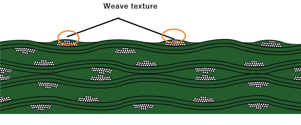
FR-4, characterized by its epoxy resin and glass fabric reinforcement, offers cost-effective insulation and mechanical strength for standard PCBs. However, in HDI constructions with multiple lamination cycles and laser-drilled vias, FR-4 can suffer from warpage, delamination, and signal degradation. The material's moderate glass transition temperature leads to softening during reflow soldering or thermal cycling, compromising via integrity. At gigahertz frequencies, its dielectric properties contribute to unacceptable insertion loss. Factory processes reveal that FR-4 struggles with coefficient of thermal expansion mismatches in multilayer stacks. Transitioning beyond FR-4 to specialized HDI PCB materials mitigates these issues for sustained performance.
Key Material Properties for HDI PCBs
Glass Transition Temperature (Tg)
High Tg materials maintain rigidity at elevated temperatures, crucial for HDI PCBs undergoing sequential lamination and lead-free soldering. The glass transition temperature marks the point where the resin shifts from glassy to rubbery state, affecting dimensional stability. Materials with higher Tg values resist warpage and z-axis expansion during thermal excursions. IPC-TM-650 method 2.4.24 provides standardized testing for Tg via differential scanning calorimetry or thermomechanical analysis. In manufacturing, selecting high Tg materials ensures compliance with multilayer build-up processes. These laminates support finer features without compromising planarity.
Dielectric Constant (DK) and Dissipation Factor (DF)
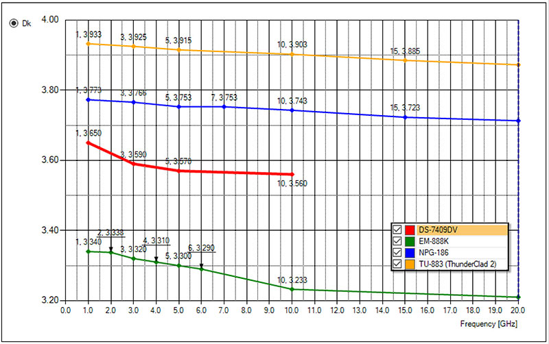
DK and DF define a material's ability to store and dissipate electrical energy, directly impacting signal integrity in high-speed HDI designs. Low DK values minimize capacitance and delay, while low DF reduces attenuation in transmission lines. Low loss dielectrics excel at frequencies above 1 GHz, preserving waveform fidelity over long traces. IPC-TM-650 methods like 2.5.5.5 outline procedures for measuring DK and DF under controlled conditions. Engineers prioritize materials where DK remains stable across temperature and humidity variations. Balancing these properties prevents crosstalk and insertion loss in dense interconnects.
Thermal Conductivity
Thermal conductivity PCB materials facilitate heat dissipation from high-power components in HDI layouts. Standard laminates conduct heat poorly in the z-direction, leading to hotspots and reliability failures. Advanced formulations incorporate fillers to enhance through-plane conductivity without sacrificing in-plane properties. This property proves vital for applications with densely packed ICs and power amplifiers. Factory thermal simulations guide material choices to match aspect ratios and via thermal resistance. Effective thermal management extends operational life under continuous loads.
Additional Properties: CTE, Moisture Absorption, and Mechanical Strength
Coefficient of thermal expansion (CTE) matching between layers prevents cracking during assembly. Low moisture absorption resists hydrolysis and ionic contamination in humid environments. Peel strength and flexural modulus ensure robustness during handling and shock. IPC-4101E specifications classify materials by these attributes for rigid and multilayer boards. Comprehensive evaluation integrates all properties for holistic HDI performance.
Types of Advanced HDI PCB Materials
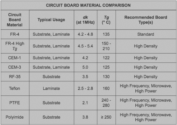
High Tg materials based on modified epoxies provide an incremental upgrade from FR-4, offering Tg values suitable for lead-free processes while retaining compatibility with standard fabrication flows. These are ideal for cost-sensitive HDI with moderate thermal demands. Polyimide resins deliver superior thermal stability and low CTE, supporting extreme environments like aerospace. For RF and microwave HDI, low loss dielectrics using polyphenylene ether or hydrocarbon resins achieve minimal DK and DF. Ceramic-filled variants boost thermal conductivity PCB performance for power-intensive designs. Each category aligns with specific stack-up requirements and process capabilities.
Related Reading: HDI PCB Materials Selection for High Frequency Applications
Material Selection Process for HDI PCBs
Begin by defining electrical, thermal, and mechanical requirements based on end-use conditions like operating frequency and power dissipation. Review datasheets against IPC-4101E slash sheets, which categorize laminates by performance grades. Simulate stack-ups to predict warpage and signal integrity using material CTE and DK values. Prototype testing via IPC-TM-650 verifies properties under real-world stress. Collaborate with fabricators early to confirm drillability and lamination compatibility. Document trade-offs, such as cost versus low loss benefits, for procurement decisions.
Related Reading: Beyond FR-4: Exploring Advanced PCB Materials for High-Frequency Applications
Best Practices in Manufacturing and Qualification
Adhere to sequential build-up processes for HDI, selecting prepregs with uniform resin content to minimize voids. Laser via formation demands materials with consistent ablation rates across layers. Post-lamination baking stabilizes dimensions before imaging. Qualification per IPC-6016 ensures HDI structures meet performance criteria for microvia reliability. Reliability assessments include thermal cycling, humidity bias, and high-frequency sweeps. Factory-driven insights emphasize traceability from laminate receipt to final assembly.
Troubleshooting Common Material-Related Issues
Warpage in high Tg materials often stems from asymmetric CTE or improper cure cycles; mitigate with symmetric stack-ups and controlled pressing. Excessive signal loss signals inadequate low loss dielectrics; verify DF at target frequencies. Thermal runaway indicates insufficient thermal conductivity PCB enhancement; incorporate embedded vias or metal cores judiciously. Delamination links to moisture preconditioning failures; bake materials per JEDEC J-STD-020 guidelines before processing. Systematic root-cause analysis using IPC-TM-650 cross-sectioning resolves these effectively.
Conclusion
Selecting the right HDI PCB materials beyond FR-4 hinges on balancing high Tg for thermal stability, low DK and DF for signal performance, and enhanced thermal conductivity for power handling. Factory-aligned choices per IPC standards ensure manufacturability and long-term reliability. Engineers gain competitive edges by prioritizing these properties in dense, high-speed designs. Proactive evaluation and testing streamline development cycles. Ultimately, informed material decisions drive innovation in compact electronics.
FAQs
Q1: What are high Tg materials and why are they essential for HDI PCBs?
A1: High Tg materials feature elevated glass transition temperatures, typically tested per IPC-TM-650 2.4.24, enabling resistance to warpage during multiple lamination cycles and reflow soldering in HDI constructions. They maintain mechanical integrity under thermal stress, supporting finer features and denser vias. Factory processes benefit from reduced rework, aligning with IPC-4101E classifications for multilayer boards. (52 words)
Q2: How do DK and DF impact high-performance HDI PCB materials?
A2: DK influences signal propagation speed, while DF dictates energy loss; low values in low loss dielectrics preserve integrity at high frequencies. Measurements follow IPC-TM-650 2.5.5.5 for accuracy across conditions. In HDI designs, minimizing these ensures low crosstalk and attenuation in microstrip lines. Optimal selection prevents performance degradation in RF applications. (58 words)
Q3: Why prioritize thermal conductivity PCB in HDI material selection?
A3: Thermal conductivity PCB materials dissipate heat efficiently from hotspots in power-dense HDI layouts, preventing component failures. Z-axis enhancement via fillers supports via thermal paths without compromising dielectrics. This property proves critical for automotive and telecom boards under sustained loads. Standardized testing validates improvements over baseline laminates. (54 words)
Q4: What standards guide HDI PCB materials qualification?
A4: IPC-6016 outlines performance specs for HDI layers, including microvia reliability, while IPC-4101E details base material properties like Tg and CTE. IPC-TM-650 provides test methods for DK, DF, and thermal conductivity. Compliance ensures factory consistency and end-product durability in high-performance scenarios. (48 words)
References
IPC-4101E — Specification for Base Materials for Rigid and Multilayer Printed Boards. IPC, 2010
IPC-TM-650 2.4.24C — Glass Transition Temperature and Z-Axis Coefficient of Linear Thermal Expansion by Thermomechanical Analysis. IPC
IPC-6016D — Qualification and Performance Specification for High Density Interconnect (HDI) Layers or Boards. IPC, 2013
JEDEC J-STD-020E — Moisture/Reflow Sensitivity Classification for Nonhermetic Solid State Surface Mount Devices. JEDEC, 2014


