Introduction
Selecting the appropriate materials for multilayer printed circuit boards (PCBs) directly impacts signal integrity, thermal management, and long-term reliability in complex electronic designs. Engineers working on multilayer PCBs face unique challenges due to the stacking of multiple copper layers separated by dielectric substrates, where material choices influence everything from impedance control to mechanical stability during fabrication and assembly. This article delivers a detailed PCB materials comparison, highlighting key aspects of FR-4 vs Rogers PCB options, high-frequency PCB materials, PCB dielectric materials, and multilayer PCB substrate selection strategies. By understanding these elements, electrical engineers can optimize designs for specific applications, whether in telecommunications, automotive systems, or high-speed computing. Factory-driven insights reveal that poor substrate selection often leads to issues like delamination or warpage in production, underscoring the need for informed decisions aligned with industry practices.
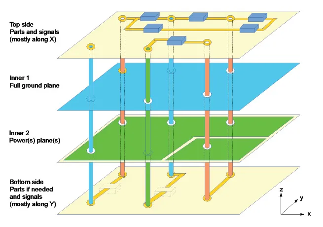
Multilayer PCBs typically consist of cores, prepregs, and copper foils bonded under heat and pressure, making dielectric properties central to performance. As layer counts increase beyond eight, material compatibility becomes even more critical to prevent issues like via failures or signal skew. This guide draws on standard manufacturing perspectives to compare materials systematically, helping engineers balance cost, performance, and manufacturability.
Why Material Selection Matters for Multilayer PCBs
In multilayer PCB substrate selection, the dielectric material serves as the insulating backbone that defines electrical performance and structural integrity. Suboptimal choices can result in higher insertion loss at elevated frequencies, excessive thermal expansion mismatches causing cracks, or reduced yield during lamination cycles. For instance, standard epoxy-based materials work well for general-purpose boards but fall short in RF applications where signal propagation demands low-loss dielectrics. Factory experience shows that aligning materials with application requirements early in the design phase minimizes costly respins and ensures compliance with reliability standards. Moreover, as electronic devices trend toward higher densities and speeds, PCB dielectric materials must support tighter tolerances in impedance and minimal crosstalk between layers.
The economic implications are significant too, with high-performance substrates increasing board costs by factors of five to ten compared to baseline options, yet delivering value through extended lifecycles. Engineers must weigh these trade-offs against project specifications, considering factors like operating environment, layer count, and assembly processes. In high-volume production, materials that facilitate consistent lamination and drilling enhance throughput, directly affecting time-to-market.
Key Properties of PCB Dielectric Materials
PCB dielectric materials are characterized by several core properties that dictate their suitability for multilayer applications. The dielectric constant (Dk), a measure of a material's ability to store electrical energy, influences signal speed and impedance; lower Dk values are preferred for high-speed designs to reduce propagation delays. Loss tangent (Df), indicating energy dissipation as heat, is crucial for minimizing signal attenuation, especially in high-frequency PCB materials where even small increases can degrade performance. Thermal properties like glass transition temperature (Tg) determine stability under soldering temperatures, while coefficient of thermal expansion (CTE) matching with copper prevents stress-induced failures during thermal cycling.
Moisture absorption also plays a vital role, as high-absorbing materials can alter Dk and lead to reliability issues like conductive anodic filamentation in humid environments. Mechanical strength, including modulus and peel strength, ensures the board withstands handling and assembly stresses in multilayer constructions. Factory testing per established methods verifies these properties, guiding substrate selection for robust outcomes.
From a manufacturing standpoint, materials must support processes like sequential lamination for high-layer-count boards, where prepreg flow and resin compatibility are key. Standards such as IPC-4101 classify base materials based on these attributes, providing a framework for consistent qualification across suppliers.
Common Materials in PCB Materials Comparison: FR-4 and Alternatives
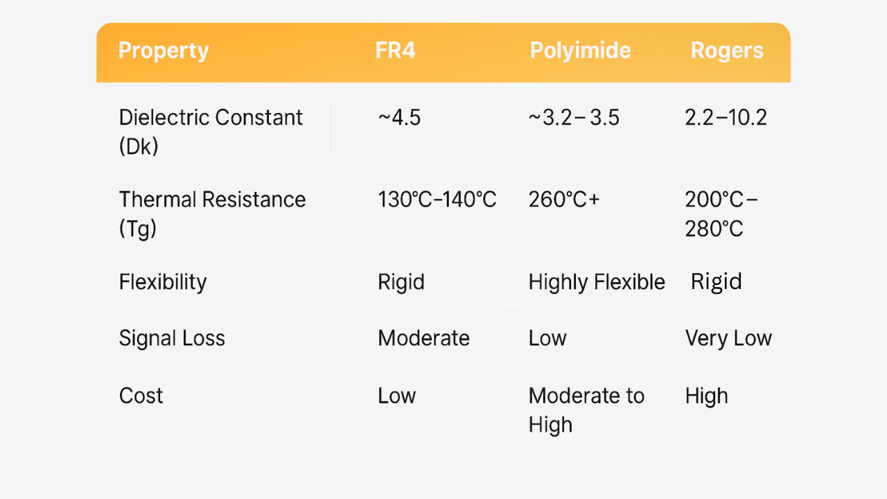
FR-4 remains the workhorse for most multilayer PCBs due to its balanced properties, cost-effectiveness, and availability in various grades for applications up to several gigahertz. Composed of woven glass fabric impregnated with brominated epoxy resin, FR-4 offers good mechanical rigidity and flame retardancy, making it ideal for consumer electronics and industrial controls. However, its relatively higher Df limits use in demanding RF scenarios, prompting comparisons with advanced options. In FR-4 vs Rogers PCB evaluations, Rogers materials stand out for their stability over frequency and temperature, catering to microwave and millimeter-wave designs.
High-frequency PCB materials, often based on PTFE or ceramic-filled composites, provide lower Dk and Df for superior signal integrity in multilayer stacks. These substrates maintain consistent electrical performance across wide bandwidths, essential for 5G infrastructure or radar systems. Polyimide-based dielectrics excel in high-temperature environments, with higher Tg supporting lead-free soldering and aerospace applications. Factory insights indicate that hybrid stacks combining FR-4 cores with high-frequency prepregs optimize cost while meeting performance needs.
Liquid crystal polymer (LCP) and other thermoplastics offer low moisture absorption and fine-line capabilities, though their higher cost suits specialized uses. Each material's viability depends on the overall stackup, where core thickness, prepreg count, and copper weight interplay.
FR-4 vs Rogers PCB: A Detailed Head-to-Head
In the FR-4 vs Rogers PCB debate, FR-4 prioritizes affordability and versatility for multilayer boards operating below 5 GHz, where its Dk stability suffices for digital signals. Rogers materials, typically ceramic-hydrocarbon or reinforced PTFE laminates, deliver exceptionally low loss tangents, enabling efficient power handling and minimal attenuation in high-frequency PCB materials applications. Electrical engineers appreciate Rogers options for their low CTE variation, reducing warpage in thick multilayers during fabrication. However, FR-4's higher moisture uptake requires bake-out procedures pre-assembly, a step less critical with Rogers substrates.
Manufacturing differences emerge in processing: FR-4 supports standard drill and plate sequences, while Rogers types demand specialized feeds, speeds, and plasma cleaning to avoid smear. Sequential build-up processes favor Rogers for controlled impedance in dense layers. Cost-wise, FR-4 enables high-volume production at lower expense, but Rogers justifies premiums in performance-critical sectors.
Reliability testing highlights FR-4's robustness in thermal shock per IPC-6012 guidelines, though Rogers edges out in humidity resistance. Selecting between them hinges on frequency needs, thermal budget, and budget constraints.
High-Frequency PCB Materials for Multilayer Designs
High-frequency PCB materials address the limitations of standard dielectrics in multilayer substrates by offering tailored electrical and thermal profiles. Ceramic-filled PTFE composites provide ultra-low Df for frequencies above 10 GHz, supporting phased-array antennas and high-speed data links. Hydrocarbon-based laminates balance low loss with mechanical stability, ideal for multilayer builds requiring blind vias and fine features. These materials exhibit minimal Dk variation with temperature, crucial for automotive radar or satellite communications where environmental extremes prevail.
In multilayer PCB substrate selection, engineers must consider prepreg compatibility, as mismatched resin systems can cause voids during pressing. Factory lamination cycles for high-frequency stacks often use vacuum assistance and lower ramp rates to preserve properties. Polyimide and PPE blends extend usability into mid-range frequencies with better cost profiles than pure PTFE.
Advanced options like low-loss FR-4 variants bridge the gap, offering improved Df for 5G base stations without full material overhaul.
Best Practices for Multilayer PCB Substrate Selection
Effective multilayer PCB substrate selection starts with defining electrical requirements, such as target impedance and frequency range, then mapping to material properties. Conduct a thorough PCB materials comparison using datasheets focused on Dk/Df at operating frequencies, alongside CTE for via reliability. Prototype stackups should incorporate representative prepregs to validate lamination viability, checking for resin flow and bond strength.
Align with standards like IPC-4101 for material specs to ensure supplier consistency. For high-layer counts, prioritize low-CTE cores to mitigate warpage, verified through shadow moire analysis. Collaborate with fabricators early to confirm drillability and plating compatibility, especially for high-frequency PCB materials.
- Dielectric Constant (Dk): FR-4 — Medium (around 4.0-4.5); High-Frequency (e.g., Rogers Types) — Low (around 2.5-3.5); Polyimide — Medium-High
- Loss Tangent (Df): FR-4 — Higher (0.015-0.025); High-Frequency — Very Low (<0.005); Polyimide — Moderate
- Glass Transition Temp (Tg): FR-4 — 130-180°C; High-Frequency — High (>250°C); Polyimide — Very High (>250°C)
- CTE (Z-Axis): FR-4 — Higher (50-70 ppm/°C); High-Frequency — Low (20-40 ppm/°C); Polyimide — Moderate
- Typical Applications: FR-4 — General Digital, Power; High-Frequency — RF/Microwave, 5G; Polyimide — High-Temp, Aerospace
- Cost Relative to FR-4: High-Frequency — 3-10x Higher; Polyimide — 2-5x Higher
Hybrid constructions, blending materials across layers, offer flexibility for mixed-signal boards.
Conclusion
Choosing the right materials for multilayer PCBs demands a holistic PCB materials comparison, balancing FR-4 vs Rogers PCB strengths with high-frequency PCB materials needs and dielectric specifics. Key properties like Dk, Df, Tg, and CTE guide multilayer PCB substrate selection, ensuring signal fidelity, thermal resilience, and fabrication success. By adhering to best practices and standards, engineers achieve reliable, high-performance boards tailored to demanding applications. Factory perspectives reinforce that proactive material vetting minimizes risks, paving the way for innovative designs in evolving electronics landscapes.
FAQs
Q1: What factors drive PCB materials comparison for multilayer designs?
A1: In PCB materials comparison for multilayers, prioritize dielectric constant, loss tangent, CTE, and Tg to match application demands. High-frequency PCB materials excel in low-loss scenarios, while FR-4 suits cost-sensitive general use. Factory alignment ensures process compatibility, reducing defects like delamination. Standards like IPC-4101 aid qualification.
Q2: When is FR-4 vs Rogers PCB a critical decision?
A2: Opt for FR-4 vs Rogers PCB based on frequency: FR-4 for under 5 GHz digital boards, Rogers for high-frequency PCB materials above 10 GHz needing low Df. Rogers offers better thermal stability but higher cost. Multilayer stackups benefit from hybrids for optimized performance.
Q3: How do PCB dielectric materials affect multilayer reliability?
A3: PCB dielectric materials impact reliability through moisture absorption and CTE mismatch, potentially causing warpage or via cracks. Select low-CTE options for high-layer counts per IPC-6012. High Tg supports assembly stresses, enhancing long-term durability in thermal cycling.
Q4: What best practices guide multilayer PCB substrate selection?
A4: Multilayer PCB substrate selection involves stackup simulation, prepreg matching, and prototype lamination trials. Compare properties qualitatively first, then test for warpage and impedance. Consult fabricators for high-frequency PCB materials to confirm drill and plate parameters.
References
IPC-4101F — Specification for Base Materials for Rigid and Multilayer Printed Boards. IPC, 2021
IPC-6012E — Qualification and Performance Specification for Rigid Printed Boards. IPC, 2017
J-STD-001H — Requirements for Soldered Electrical and Electronic Assemblies. IPC, 2020


