Introduction
Flexible printed circuit boards, or flex PCBs, enable compact designs in applications where space constraints and dynamic movement are critical. In extreme temperature environments, such as aerospace systems, automotive electronics, and industrial sensors, these boards face unique challenges that demand careful material selection. Engineers must prioritize materials that maintain electrical performance, mechanical integrity, and dimensional stability under thermal stress. This article explores flex PCB material selection for high and low temperature conditions, focusing on reliability factors guided by industry standards. By understanding these principles, designers can create robust extreme temperature flex PCBs that withstand harsh operational demands.
Why Extreme Temperature Flex PCBs Matter
Extreme temperature flex PCBs are essential in sectors where conventional rigid boards fail due to brittleness or expansion issues. High temperature flex PCBs endure heat from engines or downhole drilling, while low temperature flex PCBs operate in cryogenic storage or space vacuums. Reliability in these conditions prevents failures like delamination, cracking, or signal loss, which could compromise system safety. Material choices directly influence the coefficient of thermal expansion, glass transition temperature, and flex endurance, ensuring long-term performance. As applications grow in electric vehicles and renewable energy, selecting appropriate flex PCB materials becomes a key differentiator for design success.
Key Material Properties for Extreme Temperatures
Material selection for flex PCBs begins with evaluating thermal stability, flexibility retention, and adhesion strength across wide temperature ranges. Polyimide films excel in high temperature flex PCB applications due to their inherent resistance to thermal degradation and ability to maintain ductility. For low temperature flex PCBs, materials must resist embrittlement, preserving bend radii without fracturing. Coverlay and adhesive layers also play roles, as mismatches in properties can lead to peeling or voids during thermal cycling. Engineers assess these through standardized test methods to predict real-world behavior.
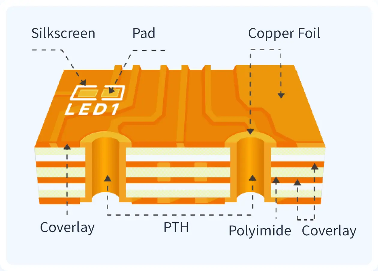
Conductors, typically copper, require careful foil treatment to match base material expansion rates. Dielectric layers provide insulation while allowing repeated flexing. Overall stackup design integrates these elements for balanced performance in extreme conditions.
Material Selection for High Temperature Flex PCBs
High temperature flex PCBs demand substrates with high glass transition temperatures and low thermal expansion to avoid warpage or conductor cracking. Polyimide remains the primary choice for its superior thermal endurance and chemical resistance, supporting applications in reflow soldering and continuous heat exposure. Liquid crystal polymer offers advantages in dimensional stability and low moisture absorption, ideal for multilayer high temperature designs. Adhesiveless constructions enhance reliability by eliminating weak interfaces prone to delamination.
Selection involves matching material properties to operating profiles, considering peak excursions and dwell times. Covercoats must bond firmly without bubbling under heat. Testing per IPC-6013 ensures qualification for these demanding uses.
Reliability improves with controlled lamination parameters that minimize voids. Copper thickness and surface finish further mitigate electromigration risks at elevated temperatures.
Material Selection for Low Temperature Flex PCBs
Low temperature flex PCBs encounter contraction stresses that can cause microcracks in brittle materials. Polyimide again proves versatile, retaining flexibility down to cryogenic levels without significant stiffening. Polyester suits milder low temperature needs but lacks the range for extremes. Coefficient of thermal expansion alignment between layers prevents stress concentrations during cooldown.
Designers prioritize materials with consistent dielectric constants across temperatures to maintain signal integrity. Adhesives must remain tacky, avoiding cold flow or separation. IPC-TM-650 test methods verify performance through thermal shock simulations.
Multilayer configurations benefit from symmetric builds to equalize contraction forces. Conductor protection via coverlay thickness ensures mechanical robustness.
Reliability Challenges and Mitigation Strategies
Reliability in extreme temperature flex PCBs hinges on managing thermomechanical stresses from coefficient mismatches. High temperatures induce creep in adhesives, while low temperatures promote fatigue in bends. Repeated cycling accelerates these, leading to trace fractures or interlayer failures. Material selection addresses this by choosing low-hysteresis films with matched expansion profiles.
IPC-2223 provides design guidelines for sectional flexibility and rigid-flex hybrids in thermal extremes. Finite element analysis predicts strain hotspots early. Plating enhancements on copper reduce oxidation vulnerabilities.
Assembly processes influence longevity, with controlled reflow profiles preserving material integrity. Environmental sealing adds protection against humidity-induced degradation.
Best Practices in Flex PCB Design for Extreme Temperatures
Start flex PCB material selection with application profiling: define peak temperatures, cycle counts, and bend frequencies. Consult IPC-6013 for qualification criteria tailored to extreme temperature flex PCBs. Prototype testing validates choices, focusing on dynamic flex combined with thermal exposure. Optimize stackups for uniform stress distribution, using thinner cores where possible.
Incorporate margins in bend radii to accommodate thermal stiffening. Select copper types with low roughness for high-frequency signals in harsh environments. Documentation of material datasheets ensures traceability.
For high temperature flex PCB, favor adhesiveless polyimide laminates. Low temperature designs benefit from reinforced edges. Iterative qualification per standards builds confidence.
Vendor collaboration refines processes without compromising specs. Lifecycle modeling forecasts mean time between failures.
Case Study: Aerospace Flex PCB Deployment
In an aerospace interconnect, engineers selected polyimide-based extreme temperature flex PCB for engine monitoring. The design endured cycles from ambient to high combustion proximity and low altitude chills. Material selection emphasized low CTE variance, tested via thermal shock per IPC-TM-650. Reliability exceeded 10,000 hours through adhesiveless construction and optimized coverlay.
Challenges included vibration coupling with thermal stress, mitigated by strain-relief features. Post-deployment analysis confirmed no delamination, validating the approach. This underscores practical flex PCB material selection impacts.
Conclusion
Designing flexible PCBs for extreme temperatures requires precise material selection balancing thermal, mechanical, and electrical demands. Polyimide dominates for both high and low temperature flex PCBs due to its proven stability, supplemented by alternatives like LCP for specialized needs. Adhering to standards like IPC-6013 and IPC-2223 ensures reliability through rigorous qualification. Best practices in stackup, testing, and assembly yield durable solutions. Engineers equipped with these insights can innovate confidently in demanding applications.
FAQs
Q1: What factors drive flex PCB material selection for high temperature flex PCBs?
A1: Polyimide films lead due to thermal stability and flexibility retention. Evaluate glass transition temperature, CTE matching, and adhesion under heat. Standards like IPC-6013 guide qualification testing. Avoid polyester for extremes, as it softens prematurely. This ensures reliability in automotive or industrial uses.
Q2: How do low temperature flex PCBs differ in material requirements?
A2: Materials must resist embrittlement and maintain ductility in cryogenic conditions. Polyimide excels with consistent properties down to low temps. Focus on contraction mismatches and dielectric stability. IPC-TM-650 thermal shock tests verify performance. Symmetric stackups prevent warping.
Q3: Why is reliability critical in extreme temperature flex PCB design?
A3: Thermal cycling causes stress leading to cracks or delamination. Proper flex PCB material selection mitigates CTE issues and fatigue. IPC-2223 design rules support robust layouts. Testing simulates field conditions for validation. Long-term integrity safeguards system operation.
Q4: What tests ensure extreme temperature flex PCB durability?
A4: Thermal shock, cycling, and flex endurance per IPC-TM-650 assess materials. High temperature flex PCB checks degradation, low temperature verifies brittleness. Combine with bend radius trials. These confirm material selection efficacy across ranges.
References
IPC-6013 — Qualification and Performance Specification for Flexible and Rigid-Flex Printed Boards. IPC
IPC-2223 — Sectional Design Standard for Flexible/Rigid-Flexible Printed Boards. IPC
IPC-TM-650 — Test Methods Manual. IPC


