Introduction
Cable shielding plays a critical role in maintaining signal integrity within electronic systems, particularly for electric engineers working on high-density PCB interconnects and harness assemblies. Electromagnetic interference (EMI) can degrade performance, leading to data errors, increased noise, and system failures in applications ranging from industrial controls to telecommunications. Understanding cable shielding types allows engineers to select the optimal configuration based on frequency range, mechanical demands, and environmental factors. This article explores cable shielding types, braided shield effectiveness, foil shield performance, grounding cable shields, cable routing EMI mitigation strategies, and differential pair cable shielding techniques. By mastering these elements, engineers can design robust systems compliant with industry standards like IPC/WHMA-A-620E. Practical insights ensure reliable operation in real-world deployments.
What Is Cable Shielding and Why It Matters
Cable shielding involves conductive layers wrapped around signal conductors to block external electromagnetic fields and prevent internal signals from radiating outward. This protection is essential in environments with high EMI sources, such as motors, power lines, and radio frequency equipment. Without effective shielding, common-mode noise couples into signals, reducing signal-to-noise ratios and violating EMC requirements. For electric engineers, selecting the right shielding directly impacts PCB-to-cable transitions and overall system reliability. Industry standards like IPC/WHMA-A-620E specify acceptance criteria for shielded assemblies, ensuring mechanical integrity and electrical performance. Ultimately, proper shielding minimizes downtime and supports compliance in demanding sectors.
Shielding effectiveness depends on coverage percentage, material conductivity, and frequency response. Foil shields offer near-complete coverage for high-frequency noise, while braids provide flexibility and low-frequency attenuation. Engineers must balance these attributes against cost, weight, and bend radius constraints. In PCB designs, unshielded cables amplify EMI risks at board edges, making shielding a non-negotiable for high-speed interfaces.
Cable Shielding Types
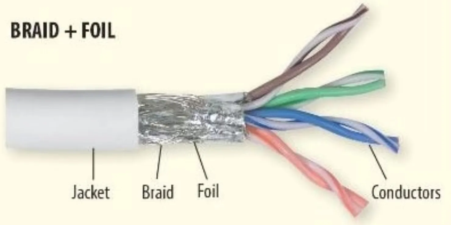
Cable shielding types primarily include foil, braid, and combination shields, each suited to specific EMI threats. Foil shields consist of thin aluminum or copper laminated to a polymer carrier, providing 100 percent coverage ideal for high-frequency interference above 1 MHz. Their uniform layer minimizes gaps where fields could penetrate, though they lack mechanical strength for flexing applications. Braided shields, formed by interwoven metal strands, typically achieve 70 to 95 percent coverage and excel in low- to mid-frequency ranges up to several hundred kHz. The open weave allows flexibility and strain relief, making braids durable in dynamic installations.
Combination shields layer foil under a braid, combining full high-frequency blockage with braid's low-impedance path and robustness. This hybrid approach delivers broadband protection, often exceeding 60 dB attenuation across decades of frequency. Foil shield performance shines in compact, static setups, while braided shield effectiveness supports vibration-prone environments. Engineers evaluate optical coverage during inspection to verify type suitability.
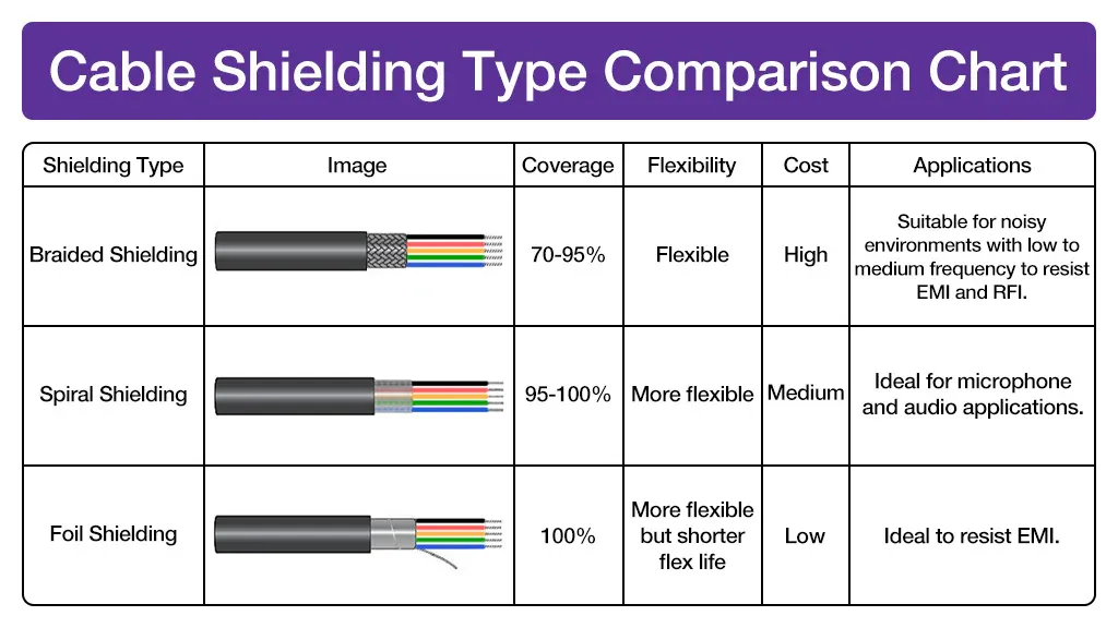
Serve or spiral shields wrap metal tape helically, offering moderate coverage around 90 percent but with potential seams that reduce high-frequency efficacy. Tape shields resemble foil but may include a drain wire for grounding. Selection hinges on application: pure foil for RF-heavy zones, braids for power-line induction.
Technical Principles of Shielding Effectiveness
Shielding operates via reflection, absorption, and multiple reflections within the shield material. At low frequencies, magnetic fields dominate, requiring high permeability or thick braids for absorption since reflection is inefficient. High-frequency electric fields reflect off thin foils due to skin effect, concentrating currents on surfaces. Braided shield effectiveness stems from low DC resistance, facilitating ground return currents that cancel induced voltages. Foil shield performance leverages total coverage, eliminating slot antennas from braid gaps.
Transfer impedance quantifies effectiveness, measuring shield impedance per unit length under external fields. IEC 62153 defines test methods for this parameter, guiding engineers in validation. Multiple layers enhance performance logarithmically, as each attenuates residuals. Environmental factors like temperature affect conductivity, though metals like copper maintain stability.
For differential signals, shielding confines fields between conductors, rejecting common-mode noise. Twisting pairs equalizes coupling, amplifying differential mode while canceling noise.
Grounding Cable Shields
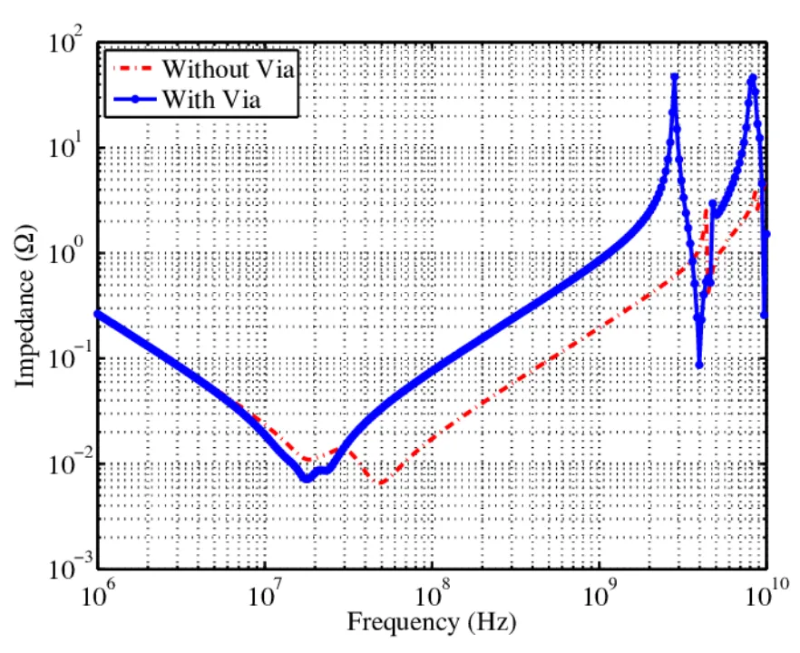
Grounding cable shields requires low-impedance paths to divert noise currents without creating loops. The preferred method uses 360-degree clamps or clamps at connector backshells, ensuring shield-to-chassis continuity over pigtails, which introduce inductance. Single-point grounding suffices for low frequencies to avoid loops, while high-speed signals benefit from both ends if grounds equipotential. IPC/WHMA-A-620E mandates secure termination without damage, verifying continuity post-assembly.
Drain wires provide backup but must contact shield fully. In unbalanced systems, ground at the signal source end; for balanced, both ends minimize potential differences. Capacitive coupling to ground serves as alternative in loops. Testing involves impedance checks under load.
Cable Routing to Minimize EMI
Cable routing EMI mitigation starts with segregation: route signal cables perpendicular to power lines, minimizing parallel runs over 1 meter. Bundle signals tightly, twisting pairs to reduce loop areas that act as antennas. Maintain 12-inch separation from high-current paths, using metal trays bonded for shielding.
Avoid sharp bends exceeding minimum radius, preserving shield integrity. Ground trays at intervals, ensuring equipotential. In enclosures, enter via shielded glands.
Elevate cables off conductive surfaces to prevent capacitive coupling.
Differential Pair Cable Shielding Techniques
Differential pair cable shielding employs twisted pairs with overall or individual foils for high-speed data. Twisting cancels far-end crosstalk, while shields block external fields. Overall braid over pairs provides mechanical protection and low-frequency shielding. Ground shields at both ends for balanced lines, using symmetric clamps.
Individually shielded pairs suit mixed signals, isolating aggressors. Foil-plus-drain suits compact designs. Route pairs as units, avoiding splits.
Best Practices for Implementation
Integrate shielding early in PCB layout, specifying transitions in schematics. Select materials matching impedance: copper for flexibility, tinned for corrosion resistance. Inspect per IPC/WHMA-A-620E, checking coverage and adhesion. Simulate EMI with field solvers pre-prototype.
Document routing diagrams, training assemblers on clamps. Qualify assemblies via triaxial tests per IEC 62153.
Conclusion
Mastering cable shielding types, from foil's high-frequency prowess to braid's versatility, empowers electric engineers to combat EMI effectively. Grounding cable shields properly, optimizing cable routing EMI strategies, and applying differential pair cable shielding techniques ensure system resilience. Adhering to standards like IPC/WHMA-A-620E and IEC 62153 delivers compliant, high-performance designs. These practices reduce noise floors, enhance data rates, and extend reliability in PCB-centric systems.
FAQs
Q1: What are the main cable shielding types for EMI protection?
A1: Cable shielding types include foil for 100 percent high-frequency coverage, braid for low-frequency effectiveness with 70-95 percent optical coverage, and combinations for broadband attenuation. Foil excels above 1 MHz due to uniform barriers, while braids handle magnetic fields via low resistance. Select based on frequency spectrum and flex needs for optimal performance.
Q2: How does braided shield effectiveness compare to foil shield performance?
A2: Braided shield effectiveness shines at low to mid-frequencies with superior mechanical durability, though coverage gaps limit high-end response. Foil shield performance provides complete blockage for RF noise but lacks flexibility. Hybrids merge strengths, often used in harnesses per IPC/WHMA-A-620E criteria.
Q3: What are best practices for grounding cable shields?
A3: Grounding cable shields demands 360-degree connections via clamps to chassis, avoiding pigtail inductance. Single-end for DC/low-freq, both ends for high-speed if equipotential. Verify continuity post-assembly to shunt noise effectively.
Q4: How can cable routing minimize EMI in differential pairs?
A4: Cable routing EMI reduction involves perpendicular paths to power cables, tight bundling of twisted pairs, and shielded trays. Separate by 30 cm minimum, ground enclosures fully. Differential pair cable shielding adds overall foil or braid for confined fields.
References
IPC/WHMA-A-620E — Requirements and Acceptance for Cable and Wire Harness Assemblies. IPC, 2017
IEC 62153 — Metallic communication cables test methods for measuring shield characteristics. IEC, 2023