Introduction
Rigid-flex PCBs integrate rigid and flexible sections into a single board, enabling compact designs in applications like wearables, medical devices, and aerospace systems. The bend radius in these boards determines how sharply the flexible portion can curve without compromising structural integrity or electrical performance. Engineers must master rigid-flex PCB bend radius calculation to prevent failures such as trace cracking or delamination during assembly and operation. This guide explores the principles behind bend radius, differentiates between static and dynamic applications, and provides structured design rules. By adhering to established practices, designers achieve reliable, long-lasting assemblies. Understanding these concepts ensures compliance with industry expectations for durability.
What Is Rigid-Flex PCB Bend Radius and Why It Matters
The bend radius refers to the smallest radius of curvature that the flexible section of a rigid-flex PCB can tolerate without mechanical or electrical damage. It measures from the inside edge of the bend to the centerline of the flex material. In rigid-flex PCB design rules, specifying the correct bend radius prevents excessive strain on copper traces and dielectrics. Poor bend radius choices lead to fatigue cracking, especially in multilayer flex areas where stresses concentrate. For electric engineers, this parameter directly impacts signal integrity, thermal management, and overall board lifespan. Neglecting it results in higher failure rates during flexing cycles or environmental stresses.
This metric gains importance in modern electronics where space constraints demand folded or contoured boards. Applications involving movement, such as robotics or foldable displays, amplify the need for precise bend radius control. Industry standards like IPC-2223 outline guidelines to balance flexibility with reliability. Engineers evaluate bend radius early in the design phase to avoid costly prototypes. Ultimately, optimal bend radius enhances product robustness and manufacturability.
Technical Principles of Bend Radius in Rigid-Flex PCBs
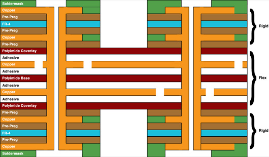
Bend radius performance stems from material properties and construction. Flexible sections typically use polyimide dielectrics with rolled annealed copper foils, which offer superior ductility compared to rigid FR-4 areas. Strain during bending concentrates on the outer traces, where tensile forces peak. The minimum bend radius for rigid-flex PCB depends on copper thickness, layer count, and dielectric modulus. Thinner constructions allow tighter radii, but multilayer stacks increase overall thickness and stress. IPC-2223 provides sectional design standards that address these interactions systematically.
Static bending occurs once during installation, imposing limited cycles, while dynamic bending involves repeated flexing, demanding larger radii to mitigate fatigue. In static cases, the flexible PCB bend radius focuses on one-time strain limits to avoid immediate cracks. Dynamic scenarios require consideration of cycle life, often thousands of bends, where micro-cracks propagate under cyclic loading. Factors like trace width, plating, and coverlay thickness further influence allowable radius. Environmental conditions, such as temperature and humidity, alter material stiffness, affecting bend behavior. Engineers model these using finite element analysis for predictive insights.
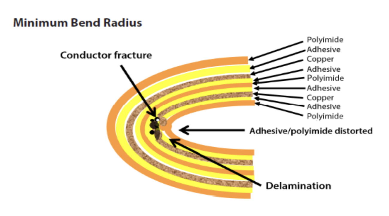
The physics involves neutral axis shift, where the bend centerline moves due to asymmetric layers. Copper ductility determines elongation before fracture, typically limiting outer fiber strain to 5-10 percent. Dielectric tear resistance complements this, ensuring coverlay integrity. Adhesiveless laminates reduce peel risks at bends. These principles guide rigid-flex PCB design rules, emphasizing gradual curvature over sharp angles.
Rigid-Flex PCB Bend Radius Calculation Methods
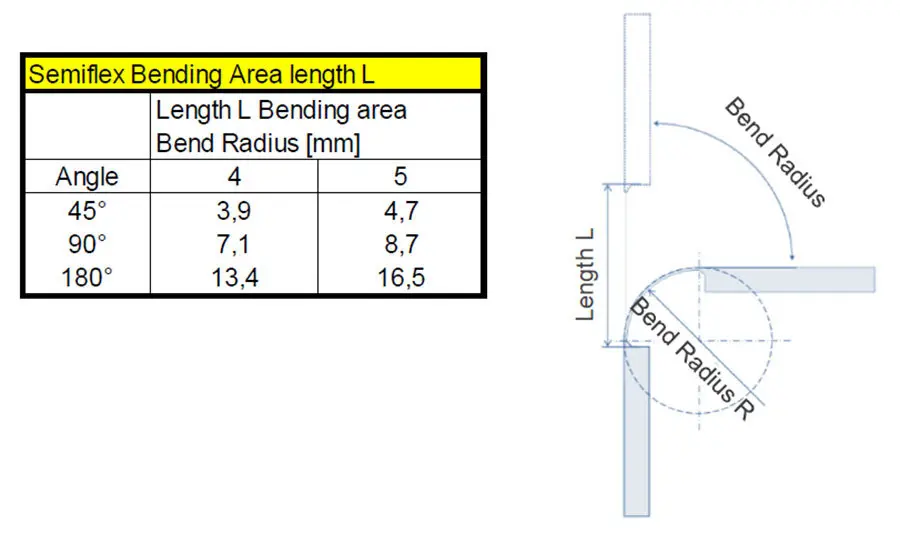
Calculating the rigid-flex PCB bend radius starts with defining application type: static or dynamic. For static bending, begin with flex section thickness, including copper, dielectric, and coverlay. Industry guidelines, such as those in IPC-2223, recommend multipliers based on layer count and copper type. Engineers compute inner radius first, then verify outer trace strain using geometric formulas. Strain epsilon equals half the thickness divided by radius, kept below material yield. Software tools simulate this, but manual checks ensure baseline accuracy.
For dynamic bending, incorporate fatigue data from standards like IPC-6013 qualification specs. Minimum bend radius for rigid-flex PCB escalates with required cycles; for example, high-cycle apps use ratios 10 to 20 times static values. Account for trace orientation: parallel to bend axis minimizes shear. Formula refinements include modulus ratio between copper and polyimide. Prototype testing validates calculations, measuring radius via bend fixtures. Iterative refinement aligns design with production capabilities.
Consider coverlay scalloping to relieve stress at edges. Multilayer flex demands wider traces in bend zones. Temperature derating adjusts radius upward for elevated operations. These steps form a robust rigid-flex PCB bend radius calculation process.
Rigid-Flex PCB Design Rules and Best Practices
Follow rigid-flex PCB design rules by placing bends away from vias, pads, or stiffeners by at least five times the flex thickness. Orient traces perpendicular to the bend line, curving them gradually with fillets. Avoid 90-degree angles, which create stress risers. Specify bend radius in fabrication drawings, noting static or dynamic use. Use adhesiveless builds for tighter radii in dynamic bending. IPC-2223 details stackup requirements for optimal flex performance.
For bend radius for static bending, position flex tails for single 180-degree folds during assembly. In dynamic zones, limit to 25 percent board area and reinforce with strain relief. Simulate bends in 3D models to predict warpage. Select copper weights under 1 oz/ft2 for flexibility. Test prototypes per IPC standards for cycle endurance. These practices ensure reliable designs.
Material selection impacts rules: polyimide excels over polyester for repeated bends. Control coverlay overlap to prevent delamination. Fabricators prefer even layer counts in flex for symmetry. Document all radii in gerber notes.
Troubleshooting Bend Radius Issues
Common failures include trace fractures from insufficient radius in dynamic apps. Inspect via cross-sectioning post-bend tests. Delamination signals poor adhesion; verify laminates meet specs. Warpage in rigid-flex transitions indicates uneven copper distribution. Measure with optical comparators and adjust stiffener placement.
Fatigue in high-cycle use traces back to sharp bends; redesign with larger radii. Electrical opens post-assembly point to static bend overstress. Use daisy-chain tests for continuity. Environmental failures demand accelerated life testing. Correct via design reviews referencing standards.
Conclusion
Mastering rigid-flex PCB bend radius ensures durable, efficient designs for demanding applications. Differentiate static and dynamic needs, apply calculation methods rigorously, and integrate best practices. Standards like IPC-2223 and IPC-6013 provide foundational guidance. Engineers gain confidence through simulation and testing. Prioritize bend radius early to streamline development. Reliable boards emerge from these disciplined approaches.
FAQs
Q1: What is the minimum bend radius for rigid-flex PCB in static applications?
A1: In static bending, where the flex occurs once during installation, the minimum bend radius for rigid-flex PCB follows IPC-2223 guidelines based on flex thickness and layers. Typically, single or double-layer flex uses a radius several times the section thickness to limit strain. Consult stackup details for precise sizing. This prevents cracking without excess material.
Q2: How does rigid-flex PCB bend radius calculation differ for dynamic bending?
A2: Rigid-flex PCB bend radius calculation for dynamic bending accounts for repeated cycles, requiring larger radii than static cases per IPC-2223 sections on flex design. Factors include cycle count, copper ductility, and strain limits. Use multipliers 10 times or more static values. Validate with fatigue testing for longevity.
Q3: What are key rigid-flex PCB design rules for flexible PCB bend radius?
A3: Rigid-flex PCB design rules emphasize traces parallel to bends, avoiding vias in flex zones, and specifying radius clearly. Flexible PCB bend radius increases with layers and copper weight. Incorporate coverlay reliefs and adhesiveless builds. These rules enhance reliability across applications.
Q4: Why is bend radius for dynamic bending larger than for static bending?
A4: Bend radius for dynamic bending must withstand fatigue from thousands of cycles, concentrating stresses on traces unlike one-time static bending. Larger radii reduce peak strain, extending life. IPC standards differentiate these for qualification. Design accordingly to match operational demands.
References
IPC-2223E - Sectional Design Standard for Flexible/Rigid-Flexible Printed Boards. IPC, 2020
IPC-6013D - Qualification and Performance Specification for Flexible Printed Boards. IPC, 2014
IPC-6013DS - Qualification and Performance Specification for Rigid/Flexible Printed Boards. IPC, 2021


