What Are Non-Plated Through-Holes (NPTH) and Why Use Them for Mounting?
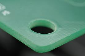
Non-plated through-holes (NPTH) are holes drilled into a printed circuit board (PCB) that do not feature a conductive copper layer on their internal walls. Unlike plated through-holes, which are typically used for electrical interconnections, NPTH are exclusively designated for mechanical functions. These holes serve as crucial mounting points, allowing the PCB to be securely fastened to an enclosure, chassis, or other hardware using screws, standoffs, or various types of fasteners.
The primary advantage of employing NPTH for mechanical mounting is their inherent electrical isolation from the board’s active circuits. This design choice effectively prevents unintended electrical connections or potential short circuits that could arise if a conductive screw or fastener were to come into contact with a plated hole. Furthermore, NPTH can be specified with larger diameters to accommodate a diverse range of fastener sizes, ensuring a secure fit without risking compromise to the board's electrical integrity.
In the subsequent sections, we will delve into the best practices for both designing and utilizing NPTH for mechanical mounting, ensuring your PCB maintains stability and full functionality even when subjected to stress or vibration.
Key Considerations for Designing PCB Mounting Holes with NPTH
When designing PCB mounting holes using NPTH, meticulous precision and foresight are absolutely essential to guarantee the board's long-term stability and operational lifespan. Here are some critical factors that demand careful consideration:
Hole Dimensions and Positional Accuracy
The diameter of the NPTH must precisely match the selected fastener size (e.g., screw or standoff), incorporating a small tolerance to facilitate easy assembly while preventing any excessive movement. For instance, a standard M3 screw has a 3 mm diameter; thus, the hole might be designed between 3.2 mm to 3.3 mm to account for manufacturing variances and ease of insertion. Mounting holes should be strategically placed in areas of the fast turn custom PCB that are clear of critical components and sensitive traces to avoid any potential interference. Typically, these holes are positioned near the board's corners to provide balanced support, though the exact placement will ultimately depend on the enclosure's design and the overall weight distribution of the assembly.
Adequate Clearance and Board Thickness
Ensure there is ample clearance surrounding the NPTH to prevent stress fractures or damage during the assembly process. A widely accepted guideline is to maintain a minimum clearance of at least 2 mm from the edge of the hole to any adjacent components or traces. The PCB's thickness significantly influences how securely it can be mounted. Standard PCB thicknesses typically range from 0.8 mm to 1.6 mm, with thicker boards generally offering superior support for heavier assemblies. Choose a board thickness that appropriately aligns with the specific mechanical demands of your project. By carefully designing the size, placement, and surrounding clearance of NPTH, you can establish a robust mounting system capable of withstanding mechanical stress and preventing damage during installation.
Effective Screw Placement Techniques for Secure PCB Mounting
Proper screw placement is a foundational element when utilizing NPTH for mechanical mounting. The correct approach ensures the PCB is firmly attached without introducing undue stress or risking damage. Here are some best practices for optimal screw placement:
Fastener Selection and Torque Control
Select screws or standoffs that are appropriately sized for the NPTH and compatible with the material of the enclosure. For instance, M2 or M3 screws are commonly employed for smaller PCBs, while larger boards may necessitate M4 or M5 screws for enhanced strength. Avoid over-tightening screws, as this can induce stress fractures in the PCB material, particularly around the mounting holes. Utilize a torque screwdriver to apply a controlled force, typically between 0.5 Nm and 1.0 Nm for M3 screws, adjusted based on the board material (e.g., FR4).
Load Distribution and Protective Elements
Incorporate washers or spacers between the screw head and the PCB to evenly distribute the load, thereby mitigating the risk of cracking. Non-conductive materials like nylon or plastic washers are often preferred to prevent any potential electrical conductivity issues. Distribute screws uniformly across the PCB to prevent uneven stress concentrations. For a rectangular board, placing screws at all four corners provides balanced support, while larger or heavier boards may require additional mounting points in the center or along the edges. Proper screw placement not only secures the PCB but also significantly reduces the risk of mechanical failure over time, especially in environments subject to frequent handling or vibration.
Supplemental PCB Support Methods for Enhanced Stability
Beyond the use of screws and mounting holes, implementing additional PCB support methods can substantially improve the board's overall stability, particularly for larger or heavier designs. Here are some highly effective strategies:
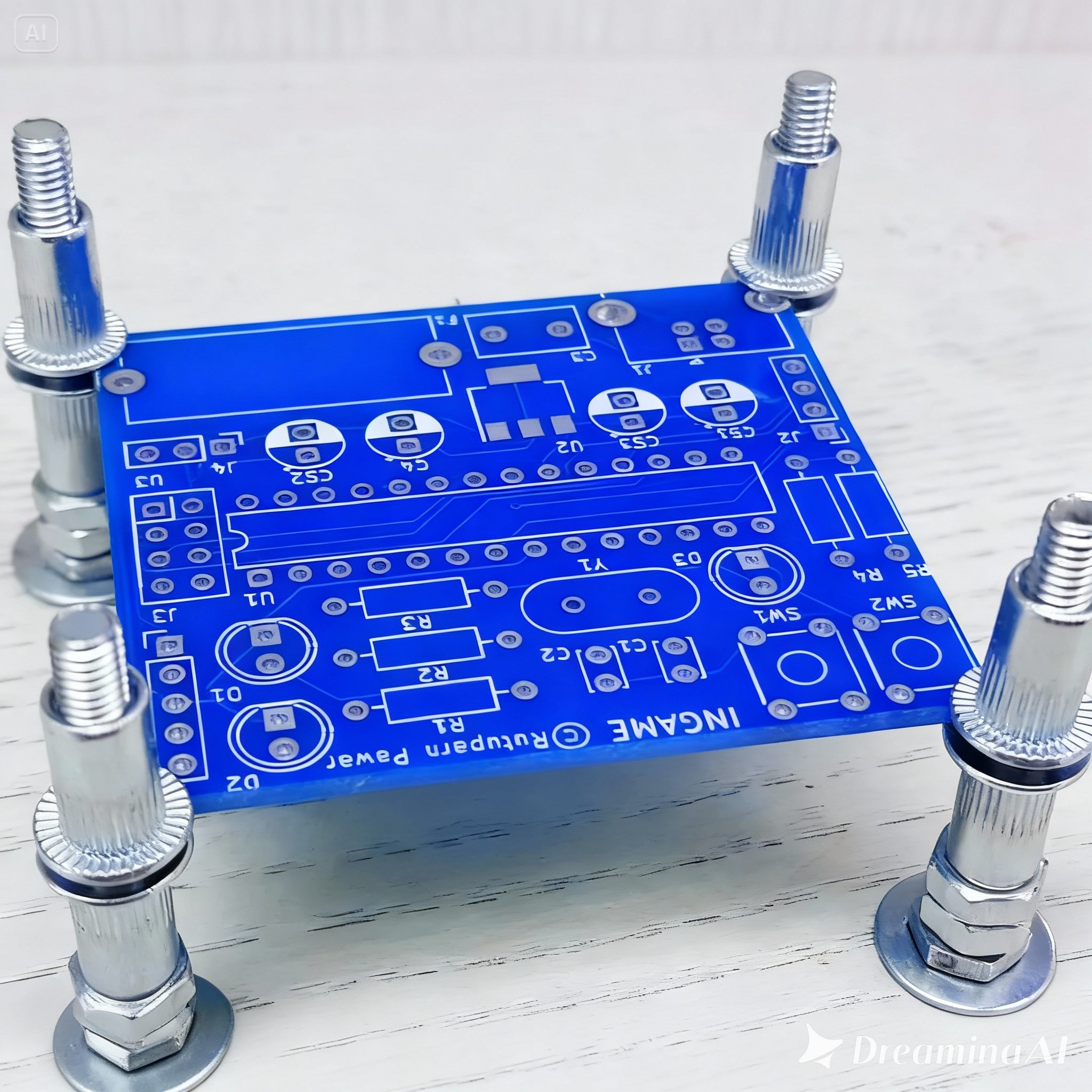
Standoffs, Support Pillars, and Edge Supports
Standoffs are cylindrical spacers designed to elevate the PCB above its mounting surface. This provides essential clearance for components on the underside and prevents potential short circuits. They are frequently used in conjunction with NPTH and are available in various heights (e.g., 5 mm to 20 mm) to suit diverse design requirements. For larger PCBs, incorporating support pillars or posts in the central areas of the board can effectively prevent sagging or undesirable flexing under its own weight. These pillars can be securely attached to the enclosure's base and precisely aligned with NPTH on the PCB. Some enclosures feature integrated slots or rails that provide direct support along the PCB's edges, thereby reducing the load on individual mounting holes. This method proves particularly beneficial for DIN rail-mounted systems or in demanding industrial applications. Implementing these diverse support methods alongside NPTH ensures that the PCB remains stable, even under challenging conditions, and significantly reduces the mechanical stress on critical components.
Strategies for Vibration Dampening to Protect PCBs
In operating environments where vibration is a significant concern, such as in automotive or industrial applications, safeguarding the PCB from excessive movement is paramount. Uncontrolled vibration can lead to loosened fasteners, fatigue in solder joints, or even catastrophic component failure. Here are some effective vibration dampening strategies for designs utilizing NPTH:
Isolating and Securing Mounting Points
Place rubber or silicone grommets between the PCB and the fastener to effectively absorb vibrations and diminish the transmission of mechanical shock. Grommets with a diameter slightly larger than the NPTH (e.g., 0.5 mm larger) typically perform best. Apply adhesive damping pads or foam materials between the PCB and the enclosure to further absorb vibrations. These pads are commonly made from materials like neoprene or silicone and are available in thicknesses ranging from 1 mm to 3 mm. Ensure that all mounting points are securely tightened, and consider using lock washers or thread-locking compounds on screws to prevent them from loosening over time due to persistent vibration.
Optimizing Hole Placement for Vibration Resistance
Strategically position NPTH mounting holes to evenly distribute vibrational forces across the board. For instance, placing holes closer to areas of high vibration can more effectively stabilize the PCB. By integrating these vibration dampening techniques, you can significantly extend the operational lifespan of your PCB and protect sensitive components from damage in harsh environments.
Stress Relief Techniques in PCB Design Using NPTH
Mechanical stress, whether originating from mounting procedures or environmental factors, can induce cracks, delamination, or premature component failure on a PCB. Utilizing NPTH for mounting presents an excellent opportunity to incorporate design features specifically for stress relief. Here’s how to minimize stress in your PCB design:
Load Distribution and Hole Clearances
Avoid relying on a single NPTH to bear the entire weight or stress exerted on the PCB. Instead, distribute the load across multiple mounting holes to reduce localized stress concentrations. For a medium-sized PCB (e.g., 100 mm x 150 mm), it is recommended to use at least four mounting points. Design NPTH with slightly larger diameters than the fastener to allow for minor misalignments during assembly. This larger clearance reduces stress caused by forced fitting.
Reinforcement and Thermal Expansion Consideration
For PCBs subjected to high mechanical stress, consider adding reinforcement around the NPTH. This could include thicker copper rings (even if non-plated) or additional fiberglass layers within multi-layer boards to strengthen the area. In environments with fluctuating temperatures, materials expand and contract at varying rates. Design NPTH with sufficient clearance to accommodate the thermal expansion of the PCB (typically 10-15 μm per degree Celsius for PCB FR4 material) and prevent cracking. By prioritizing stress relief during the design phase, you can create a PCB capable of withstanding both mechanical and thermal challenges without compromising its performance.
Enclosure Design Considerations for NPTH Mechanical Mounting
The enclosure or chassis housing the PCB plays a crucial role in the overall effectiveness of NPTH mechanical mounting. A well-designed enclosure complements the PCB's mounting strategy and enhances the assembly's durability. Here are some essential tips for enclosure design:
Alignment, Space, and Material Selection
Ensure that the enclosure features pre-drilled holes or integrated mounting bosses that align perfectly with the NPTH on the PCB. Misalignment can introduce unnecessary stress or significantly complicate assembly. A tolerance of ±0.1 mm is ideal for achieving precise alignment. Design the enclosure with ample internal space to comfortably accommodate the PCB, all components, and any necessary standoffs or spacers. For example, a clearance of at least 5 mm above tall components like capacitors or connectors prevents contact with the enclosure lid. Choose enclosure materials that are appropriate for the application's specific requirements. Plastic enclosures are lightweight and non-conductive, whereas metal enclosures offer superior shielding and durability but may necessitate insulating spacers to prevent short circuits with the PCB.
Integrated Ventilation
If the PCB generates heat during operation, design the enclosure with strategically placed ventilation slots or holes to facilitate heat dissipation. Crucially, ensure that these ventilation features are positioned away from mounting points to avoid weakening the structural integrity. A thoughtfully designed enclosure not only protects the PCB but also guarantees that the NPTH mounting system functions as intended, providing a secure and stable setup.
Common Pitfalls to Avoid When Using NPTH for Mechanical Mounting
Despite the best intentions, certain errors can undermine the effectiveness of NPTH for mechanical mounting. Here are some common mistakes to be mindful of:
Design and Environmental Oversights
Using plated holes for mounting: Plated through-holes can inadvertently create electrical connections with conductive fasteners, potentially leading to short circuits. Always use NPTH for mechanical mounting unless a specific grounding connection is explicitly required. Ignoring adequate clearance: Positioning NPTH too close to components or the board edges can result in cracks or interference during assembly. Always adhere strictly to recommended clearance guidelines. Neglecting environmental factors: Failing to account for environmental stressors such as vibration, thermal expansion, or humidity can lead to premature mechanical failure over time. Always design with the anticipated operating environment firmly in mind.
Skipping Prototyping
Omitting the prototyping phase: Without thoroughly testing the mounting design in a prototype, potential alignment issues or critical stress points may go undetected until full-scale production, leading to expensive and time-consuming redesigns. By diligently avoiding these common errors, you can ensure a significantly more reliable and durable mounting solution for your PCB.
Conclusion: Mastering NPTH for Robust Mechanical Mounting
Non-plated through-holes are an indispensable tool for mechanical mounting in PCB design, offering a secure and electrically isolated method for attaching boards to various enclosures or chassis. By rigorously adhering to the best practices and design tips outlined in this guide—including optimizing PCB mounting holes, ensuring meticulous screw placement, enhancing overall PCB support, implementing effective vibration dampening strategies, designing for critical stress relief, and carefully considering enclosure design—you can create robust and exceptionally reliable assemblies that are built to endure over time.
Whether you are engaged in a small-scale hobby project or developing a complex industrial application, paying meticulous attention to the details of NPTH design will yield significant benefits in terms of improved performance and enhanced durability. Invest the necessary time to carefully plan your mounting strategy, and you will effectively circumvent common pitfalls while achieving a professional-grade result.


