Introduction
Printed Circuit Boards (PCBs) are the backbone of modern electronics, ensuring reliable performance in everything from consumer devices to industrial systems. However, contamination on PCBs, particularly from flux residue and ionic contaminants, poses significant risks to functionality and longevity. For electrical engineers, understanding PCB cleaning methods and contamination prevention is vital to maintaining high standards of quality and reliability. This article explores the critical aspects of PCB cleaning, the impact of flux residue, and the dangers of ionic contamination. By addressing these issues with industry best practices and adherence to recognized standards, engineers can mitigate risks and ensure optimal performance. The focus here is on actionable insights and technical principles to help professionals navigate these challenges effectively.
Why PCB Cleaning Matters
PCB cleaning is a crucial step in the manufacturing and assembly process to remove contaminants that can compromise electrical performance. Flux residue, often left behind after soldering, can attract moisture and lead to corrosion over time. Ionic contamination, which includes salts and other conductive residues, can cause short circuits or degrade insulation resistance. These issues are particularly problematic in high reliability applications such as aerospace or medical devices. Without proper cleaning, contaminants can result in field failures, reduced product lifespan, and costly rework. For electrical engineers, ensuring cleanliness aligns with stringent industry requirements and directly impacts the dependability of electronic systems under varying environmental conditions.
Technical Principles of Contamination on PCBs
Flux Residue and Its Effects
Flux is used during soldering to remove oxides and promote better bonding between components and the PCB. However, residues from flux can remain on the board if not adequately cleaned. These residues often contain organic acids or halides that are hygroscopic, meaning they absorb moisture from the environment. Over time, this can lead to corrosion of metallic traces and pads, ultimately affecting signal integrity. In severe cases, flux residue can contribute to dendritic growth, a phenomenon where conductive filaments form between adjacent conductors, causing shorts.
Ionic Contamination Mechanisms
Ionic contamination refers to the presence of conductive particles, such as salts or ionic residues from manufacturing processes, on the PCB surface. These contaminants can originate from human handling, environmental exposure, or materials used in fabrication. When exposed to humidity, ionic residues can dissolve and create conductive paths, lowering insulation resistance between traces. This often results in leakage currents or catastrophic failures. The risk is amplified in high density designs where spacing between conductors is minimal, making even small amounts of contamination problematic.
Standards for Assessing Contamination
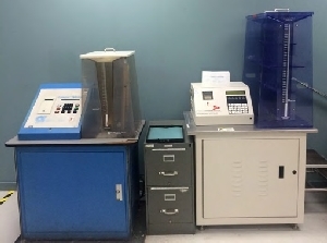
Industry standards provide clear guidelines for evaluating and controlling contamination levels on PCBs. The IPC TM 650 2.3.25 standard outlines the Resistivity of Solvent Extract (ROSE) test, a widely used method to quantify ionic contamination by measuring the resistivity of a solvent after it extracts residues from the board. Adherence to such standards ensures that cleanliness levels meet the necessary thresholds for reliability, particularly in critical applications.
Practical Solutions for PCB Cleaning
Cleaning Methods to Remove Flux Residue
Effective PCB cleaning begins with selecting the appropriate method based on the type of flux and assembly requirements. Aqueous cleaning, which uses water based solutions, is suitable for water soluble fluxes. It often involves immersion or spray systems to remove residues, followed by thorough drying to prevent moisture retention. For no clean fluxes, which are designed to leave minimal residue, solvent based cleaning with isopropyl alcohol or specialized formulations can be applied using brushes or ultrasonic baths. Each method must be tailored to the specific flux chemistry to avoid damaging components or the board itself.
Preventing Ionic Contamination
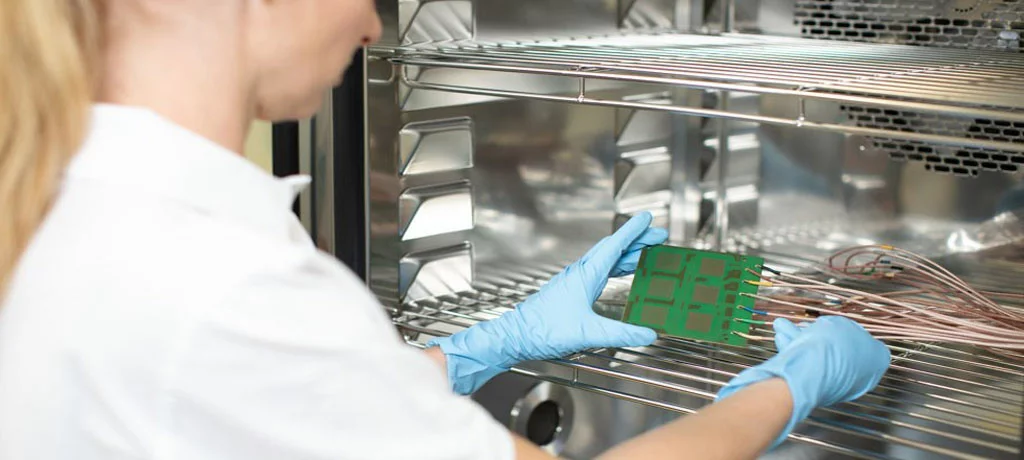
Preventing ionic contamination starts with controlling the manufacturing environment. Cleanroom conditions, as outlined in ISO 14644 1:2015 for airborne particulate cleanliness, can significantly reduce the risk of environmental contaminants settling on PCBs during production. Additionally, proper handling procedures, such as wearing gloves and using antistatic equipment, minimize the transfer of salts from human contact. Engineers should also ensure that raw materials, including laminates and solders, meet purity requirements to avoid introducing ionic residues during fabrication.
Testing for Cleanliness
Regular testing for cleanliness is essential to validate the effectiveness of cleaning processes. The ROSE test, as specified in IPC TM 650 2.3.25, provides a quantitative measure of ionic contamination by assessing the conductivity of a solvent extract. Surface Insulation Resistance (SIR) testing, detailed in IPC TM 650 2.6.3.7, evaluates the board's resistance to leakage currents under controlled humidity and temperature conditions. These tests help engineers identify contamination issues early and adjust cleaning protocols accordingly to meet industry benchmarks.
Best Practices for Footprint Contamination Control
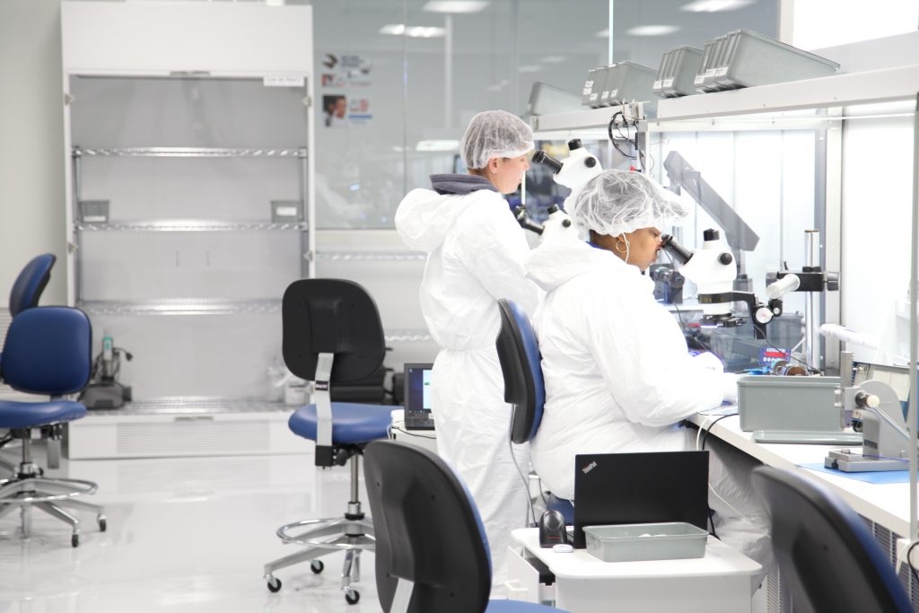
Footprint contamination, referring to residues or particles in the areas where components are mounted, can interfere with soldering and bonding. To mitigate this, engineers should ensure that stencil printing and placement processes are performed in controlled environments to avoid dust or debris accumulation. Post soldering inspection under magnification can help detect residual flux or particles in critical areas. Implementing a robust cleaning schedule, aligned with standards like IPC A 610H for acceptability of electronic assemblies, ensures that footprint areas remain free of contaminants that could affect long term reliability.
Troubleshooting Common Contamination Issues
For electrical engineers, addressing contamination related failures often involves a systematic approach to troubleshooting. If a board exhibits intermittent failures or corrosion, the first step is to inspect for visible flux residue or discoloration around solder joints. Conducting an SIR test can confirm whether ionic contamination is the root cause by revealing reduced resistance values. In cases of persistent issues, revisiting the cleaning process parameters, such as solvent concentration or rinse duration, may be necessary. Additionally, reviewing environmental controls and handling practices can uncover sources of contamination that were previously overlooked. This methodical process ensures that issues are resolved without compromising the integrity of the assembly.
Conclusion
PCB cleaning and contamination control are indispensable for ensuring the reliability and performance of electronic assemblies. Flux residue and ionic contamination pose significant threats by promoting corrosion and electrical failures, particularly in demanding applications. By adhering to established industry standards and implementing effective cleaning and prevention strategies, electrical engineers can mitigate these risks. Regular testing and meticulous attention to environmental and handling factors further enhance the quality of PCBs. Ultimately, a proactive approach to managing contamination safeguards the integrity of electronic systems and supports long term operational success in diverse industries.
FAQs
Q1: What are the main causes of flux residue on PCBs?
A1: Flux residue on PCBs primarily results from soldering processes where flux is used to facilitate bonding. Incomplete cleaning after soldering leaves behind organic acids or halides. Environmental factors like humidity can worsen the impact by attracting moisture to these residues. Following standards like IPC A 610H helps ensure thorough removal during the assembly phase.
Q2: How does ionic contamination affect PCB performance?
A2: Ionic contamination introduces conductive particles, such as salts, on PCB surfaces, reducing insulation resistance. This can lead to leakage currents or short circuits, especially under humid conditions. Performance issues often manifest as intermittent failures or complete breakdowns. Testing per IPC TM 650 2.3.25 can quantify contamination levels and guide corrective actions.
Q3: What are the best methods for PCB cleaning to avoid contamination?
A3: Effective PCB cleaning methods include aqueous cleaning for water soluble fluxes and solvent based cleaning for no clean fluxes. Ultrasonic baths or manual brushing with appropriate solutions can target residues. Controlling the environment per ISO 14644 1:2015 standards prevents recontamination. Tailoring the method to flux type ensures optimal results without damage.
Q4: Why is footprint contamination a concern for electrical engineers?
A4: Footprint contamination in component mounting areas can disrupt soldering and bonding, leading to poor connections. Dust, flux residue, or ionic particles in these zones may cause reliability issues over time. Regular inspection and adherence to cleanliness standards like IPC A 610H are critical to prevent failures in high density PCB designs.
References
IPC TM 650 2.3.25 — Detection and Measurement of Ionizable Surface Contaminants by Resistivity of Solvent Extract (ROSE). IPC, Current Version.
IPC TM 650 2.6.3.7 — Surface Insulation Resistance, Fluxes. IPC, Current Version.
IPC A 610H — Acceptability of Electronic Assemblies. IPC, 2021.
ISO 14644 1:2015 — Cleanrooms and Associated Controlled Environments, Part 1: Classification of Air Cleanliness by Particle Concentration. ISO, 2015.


