Introduction: Why Rogers PCB Design Matters in the Modern Era
In the rapidly evolving landscape of telecommunications, aerospace, and high-speed computing, standard FR-4 materials often fall short. As signal frequencies climb into the Gigahertz (GHz) range, the physical properties of the printed circuit board (PCB) substrate become a critical component of the circuit itself. This is where Rogers PCB design comes into play.
Rogers Corporation high-frequency laminates are the industry standard for RF (Radio Frequency), microwave, and high-speed digital designs. Unlike traditional epoxy-based boards, Rogers materials offer superior dielectric constant stability, low dissipation factors, and excellent thermal management. Designing with Rogers requires a specialized mindset—balancing electrical performance with mechanical manufacturability.
In this guide, we will dive deep into the nuances of Rogers materials, layout strategies, and how to transition from a theoretical concept to a high-performance physical prototype.
Why Rogers Materials Define High-Frequency Success
The core of any Rogers PCB design lies in its material science. While FR4 is an epoxy/glass laminate, Rogers substrates—such as the RO4000 or RO3000 series—are often ceramic-filled hydrocarbons or PTFE-based materials.
Key Performance Metrics:
-
Dielectric Constant (Dk) Stability: Rogers materials maintain a stable Dk across a broad range of frequencies and temperatures, which is critical for maintaining phase consistency.
-
Low Dissipation Factor (Df): By reducing the energy lost as heat (dielectric absorption), Rogers materials ensure that signal strength is preserved from the transmitter to the antenna.
-
CTE (Coefficient of Thermal Expansion) Matching: Their thermal expansion coefficient is closely matched to copper, ensuring high reliability during thermal cycling.
Comprehensive Material Selection Matrix
Selecting the right laminate is the foundation of your design. The choice depends on whether you are prioritizing cost, ease of fabrication, or absolute electrical performance.
Table 1: Comparative Analysis of Common Rogers Laminates
| Material Series | Substrate Base | Dielectric Constant (Dk) | Dissipation Factor (Df) | Typical Application |
| RO4003C | Hydrocarbon/Ceramic | 3.38 | 0.0027 | Multi-layer RF designs, LNBs |
| RO4350B | Hydrocarbon/Ceramic | 3.48 | 0.0037 | Base station antennas, 5G |
| RO3003 | PTFE/Ceramic | 3.00 | 0.0010 | 77 GHz Automotive Radar |
| RT/duroid 5880 | Glass Reinforced PTFE | 2.20 | 0.0009 | Aerospace, Military Radar |
Mastering Precision Impedance Control
In high-speed and RF layouts, impedance mismatches lead to signal reflections and EMI issues. Because Rogers materials have much tighter Dk tolerances (often ±0.05) than FR4, they allow for much more predictable impedance modeling.
Achieving a perfect 50-ohm transmission line requires more than just knowing your trace width. You must account for copper thickness, dielectric height, and even the solder mask's influence. To bridge the gap between theory and fabrication, designers should leverage an accurate Rogers PCB impedance calculator and practical guide to determine the exact geometries required for microstrip or stripline configurations. This precision ensures that the manufactured board performs identically to the simulated model.
Key Variables in Impedance Calculation:
-
Trace Width (W): The primary control mechanism.
-
Copper Weight (T): Typically 0.5oz or 1oz for RF layers.
-
Dielectric Thickness (H): The distance between the signal layer and the reference plane.
-
Surface Roughness: At frequencies above 10GHz, the roughness of the copper foil increases the effective resistance (Skin Effect).
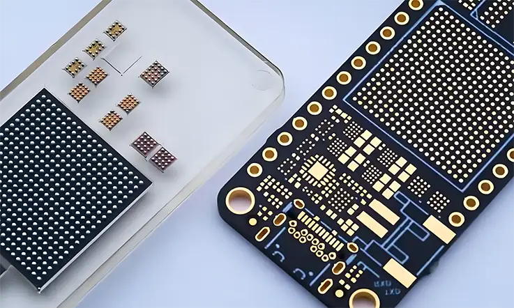
Advanced Stack-up Strategies: Hybrid Designs
One of the most cost-effective methods in Rogers PCB design is the "Hybrid Stack-up." Since Rogers laminates are more expensive than FR4, designers often use Rogers for the critical high-frequency signal layers and FR4 for the internal power and ground planes.
Benefits of Hybrid PCBs:
-
Cost Optimization: Reduces material spend by 30-50%.
-
Structural Integrity: FR4 provides better mechanical rigidity for large boards.
-
Standard Fabrication: RO4000 series can be processed using standard FR4 lead-free manufacturing cycles.
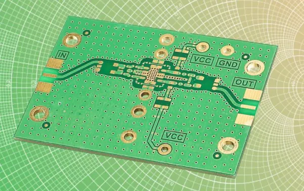
High-Frequency Amplifier Design with Rogers
Amplifiers are the heart of RF systems, and they are notoriously sensitive to substrate choice. In an amplifier circuit, the PCB isn't just a carrier; it acts as a tuning element.
The choice of copper weight and surface finish (such as ENIG or Silver) can significantly impact the gain and noise figure of an amplifier. Furthermore, heat dissipation is a major concern. When working on these complex circuits, understanding the specific design considerations for high-frequency amplifiers using Rogers PCB is essential. These considerations include parasitic capacitance reduction and thermal via placement to ensure the amplifier doesn't overheat during high-power transmission.
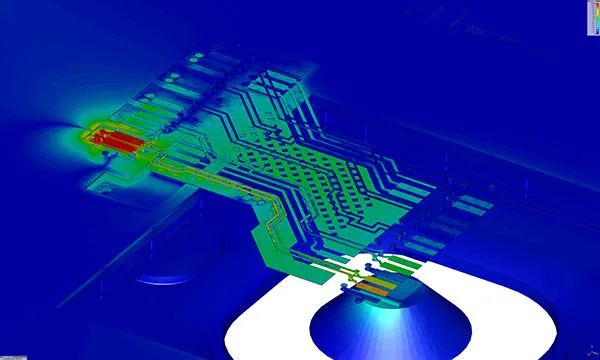
Signal Integrity and Electromagnetic Interference (EMI)
High-frequency designs are inherently prone to crosstalk and radiation. In Rogers PCB design, the goal is to keep the energy contained within the transmission lines.
-
Via Shielding: Surrounding high-speed traces with "via fences" to prevent lateral EMI leakage.
-
Ground Plane Continuity: Ensuring a solid, unbroken reference plane directly beneath RF traces to provide a low-impedance return path.
-
Edge Launch Connectors: Selecting the right SMA or K-connector and designing the transition zone (launch) to match the PCB's impedance.
Conclusion: Future-Proofing with Rogers Design
As we push toward 6G and more complex satellite constellations, the precision offered by Rogers Corporation's materials is no longer optional—it is a requirement. By understanding the interplay between material properties, impedance accuracy, and thermal management, designers can create hardware that exceeds the limits of standard electronics.
Investing time in the early stages of Rogers PCB design—from selecting the RO3003 laminate for radar to using a hybrid stack-up for 5G base stations—ensures long-term reliability and peak performance in the most demanding RF environments.
FAQs
Q1: Can I use standard FR-4 lead-free solder processes for Rogers PCBs?
A1: Most Rogers 4000 series materials are compatible with standard lead-free soldering temperatures. However, PTFE-based materials (like the 3000 series) may require specialized profiles to prevent substrate deformation or delamination.
Q2: Why is "Plasma Desmear" so important in Rogers PCB manufacturing?
A2: Rogers materials, especially those containing PTFE, are chemically inert. Standard chemical desmearing cannot effectively clean or "activate" the hole walls for plating. Plasma treatment uses ionized gas to ensure a clean surface, which is critical for reliable copper bonding.
Q3: Is it possible to mix different types of Rogers materials in a single board?
A3: Yes, this is known as a "Multi-material Rogers Stack-up." While possible, it is extremely difficult due to differing resin flow rates and press temperatures. It requires a manufacturing partner with extensive experience in hybrid lamination cycles.
Q4: How does moisture absorption affect Rogers PCB performance?
A4: Rogers materials have significantly lower moisture absorption (often <0.06%) compared to FR-4 (~0.20%). High moisture absorption can change the dielectric constant of the board, leading to unpredictable impedance shifts and signal phase errors in sensitive RF circuits.