Why Are Power Planes Essential in PCB Design?
Power planes are broad copper areas on a printed circuit board (PCB) that distribute power or ground signals efficiently. These copper regions ensure stable voltage delivery, minimize electrical noise, and support signal clarity, especially in multilayer boards where entire layers are dedicated to power or ground.
The choice between a solid or hatched power plane shapes how your PCB manages electrical flow, heat, and production challenges. Selecting the wrong type could lead to issues like signal interference, overheating, or higher costs. Let’s explore what sets these two approaches apart.
Understanding Power Plane Basics
A power plane, often called a copper pour, creates a low-resistance path for current, reducing voltage fluctuations and enhancing circuit reliability. By covering large areas with copper, it also helps shield sensitive signals from interference, a critical factor in complex designs.
Why the Fill Type Matters
The fill type—solid or hatched—affects not just electrical performance but also manufacturing ease and material costs. AIVON’s engineering team emphasizes that choosing the right fill type early in the design process can prevent costly revisions later.
What Makes a Solid Power Plane the Right Choice?
A solid power plane is a continuous sheet of copper spread across a PCB layer, commonly used for power or ground distribution. Its seamless design excels in demanding applications, but it comes with trade-offs.
Superior Electrical Performance
With no gaps in the copper, solid planes offer minimal resistance, enabling them to handle high currents—often 5-10 amps—with negligible voltage drops. This makes them ideal for power-hungry circuits like motor controllers or LED drivers. They also reduce signal return path inductance, ensuring clean transmission in high-speed designs.
Effective Heat and EMI Management
Solid planes spread heat evenly, lowering component temperatures by as much as 10-15°C compared to other fill types, according to AIVON’s thermal analysis data. Their unbroken surface also blocks electromagnetic interference (EMI) effectively, reducing noise by up to 25% in high-frequency circuits like RF modules.
Manufacturing Considerations
However, solid planes use more copper, raising material costs, especially for larger boards. They can also cause uneven thermal expansion during soldering, potentially warping the PCB if copper isn’t balanced across layers. Etching large copper areas may also slow production due to the need for more etching solution.
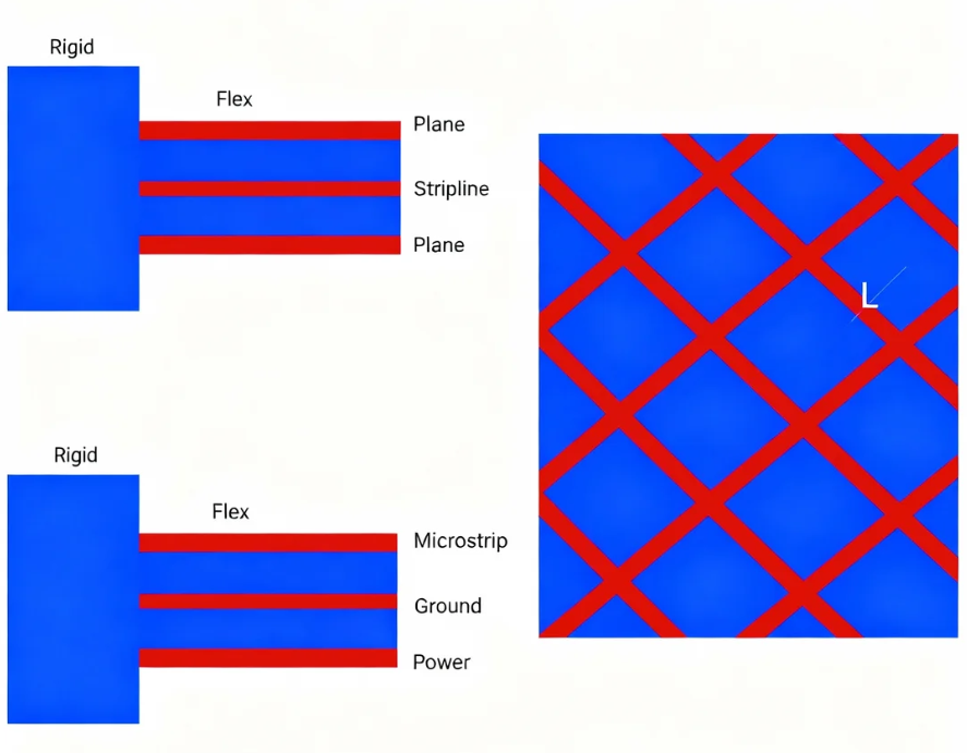
When Should You Opt for a Hatched Power Plane?
A hatched power plane uses a grid or crosshatch pattern of copper instead of a solid layer. While less common in modern high-performance HDI PCBs, this approach still suits specific scenarios.
Cost and Manufacturing Benefits
Hatched planes use significantly less copper—sometimes 30-50% less than solid fills—lowering material and etching costs. The grid structure also reduces thermal stress during manufacturing, minimizing the risk of board warping, which is particularly valuable for thin or flexible PCBs.
Suitable Applications
For low-power circuits, such as basic analog designs or those operating below 50 MHz, hatched planes provide sufficient performance without the expense of solid fills. They’re also useful in prototyping, where cost savings and flexibility outweigh the need for top-tier electrical performance.
Limitations to Consider
The gaps in a hatched plane increase electrical resistance and inductance, which can cause voltage drops in high-current designs. These gaps also allow more EMI to pass through, making hatched planes less effective for high-speed or RF applications. Heat dissipation is another weak point, as the reduced copper mass limits thermal spreading.
How Do Solid and Hatched Planes Compare?
Choosing between solid and hatched power planes depends on your project’s priorities. Here’s a breakdown of key factors:
● Current Handling: Solid planes excel with high currents (5-10A), while hatched planes are better for low-current designs (1-3A).
● EMI Protection: Solid planes reduce EMI by 20-30%, while hatched planes offer minimal shielding due to their grid structure.
● Thermal Efficiency: Solid planes dissipate heat better, preventing hotspots, whereas hatched planes may struggle in high-power setups.
● Cost and Manufacturing: Hatched planes save on copper and reduce warping risks, making them more economical for simpler boards.
This comparison highlights why solid planes dominate in high-performance designs, while hatched planes remain a practical choice for budget-conscious or less demanding projects.
When Is a Solid Power Plane the Best Fit?
Solid power planes shine in scenarios where performance is non-negotiable. Use them when:
● Your design handles high currents, such as in power supplies or automotive electronics.
● You’re working with high-speed signals (e.g., above 100 MHz) that require low noise and stable return paths.
● EMI shielding is critical, as in wireless or RF circuits.
● Heat-generating components, like power amplifiers, need efficient thermal spreading.
AIVON’s design team notes that solid planes are standard in multilayer PCBs for data centers or telecommunications due to their reliability under demanding conditions.
When Does a Hatched Power Plane Make Sense?
Hatched power planes are a smart choice for less complex or cost-driven projects. Consider them for:
● Budget-limited designs where performance demands are low, such as simple consumer electronics.
● Low-frequency circuits (under 50 MHz) that don’t need extensive EMI protection.
● Flexible PCBs, where the grid pattern reduces mechanical stress during bending.
● Early-stage prototypes, allowing cost-effective testing before finalizing a design.
For example, AIVON’s engineers often recommend hatched planes for initial prototype runs to keep costs down while validating functionality.
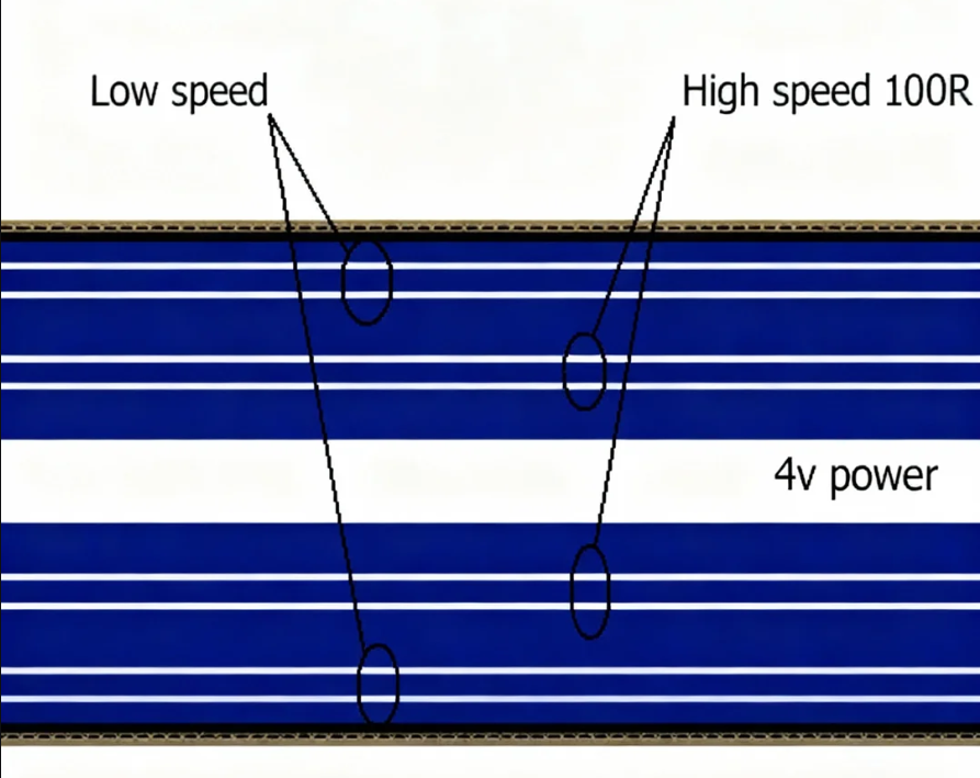
What Are the Benefits of Copper Pours in General?
Whether solid or hatched, copper pours enhance PCB performance in several ways:
● Stable Power Delivery: They minimize voltage fluctuations, ensuring consistent component operation.
● Noise Reduction: Copper pours lower ground bounce and crosstalk, especially in high-frequency circuits.
● Balanced Manufacturing: Filling unused areas with copper reduces etching time and stabilizes board structure, potentially cutting production costs by 10-15%.
● Mechanical Strength: Even copper distribution across layers prevents warping or cracking during fabrication.
These advantages make copper pours a cornerstone of efficient PCB design, regardless of the fill type.
How Can You Optimize Power Plane Design?
To get the most out of your power plane, follow these practical guidelines:
● Distribute Copper Evenly: Balance copper across layers to avoid warping, especially with solid planes.
● Incorporate Thermal Reliefs: Use copper spokes when connecting pads to planes to ease soldering by preventing excessive heat absorption.
● Check Clearances: Maintain 8-10 mil gaps between planes and unrelated traces to prevent short circuits.
● Simulate Before Building: Use design tools to model current flow, heat distribution, and EMI to catch issues early.
● Collaborate with Fabricators: Consult a large PCB manufacturer to align your design with their etching and material capabilities.
These steps help ensure your power plane supports both performance and manufacturability.
How to Choose the Right Power Plane for Your PCB?
The decision between solid and hatched power planes hinges on your project’s electrical, thermal, and budgetary needs. Solid planes are the go-to for high-power, high-speed, or heat-sensitive designs due to their superior current handling, EMI shielding, and heat distribution. Hatched planes, however, offer a cost-effective alternative for simpler circuits or prototypes where performance demands are lighter.
By weighing factors like current requirements, signal speed, and manufacturing constraints, you can select a power plane that aligns with your goals. AIVON’s team advises running simulations and consulting with fabricators to fine-tune your choice, ensuring a PCB that delivers reliability without breaking the budget.


