Introduction
Flex PCBs and rigid-flex PCBs have become essential in modern electronics, enabling compact designs for applications like wearables, medical devices, and aerospace systems. These boards combine the flexibility of thin polyimide substrates with the rigidity needed for mounting components. However, manufacturing and operational challenges arise from uneven material properties and stresses. Copper balancing addresses these by ensuring uniform copper distribution across layers, which directly impacts PCB reliability and mechanical stability. Without it, imbalances lead to warpage, delamination, and failures during bending or thermal cycling.
This article explores the principles, benefits, and practices of copper balancing tailored for electric engineers working with flex PCB and rigid-flex PCB designs. Copper balancing is particularly vital in flex and rigid-flex constructions because of their multilayer stackups and dynamic use cases. Factory processes like lamination and plating amplify any copper asymmetry, causing dimensional instability. Engineers must prioritize this during design to meet performance demands. By achieving balance, boards maintain flatness post-fabrication and endure real-world stresses. The result is higher yield rates and longer service life, aligning with quality control in production environments.
What Is Copper Balancing and Why It Matters for Flex and Rigid-Flex PCBs
Copper balancing refers to the practice of distributing copper traces, planes, and fills symmetrically within each layer and evenly between opposing layers of a PCB. In flex PCBs, this means matching copper coverage percentages, typically aiming for differences under 10 percent per layer pair. For rigid-flex PCBs, it extends to both flexible and rigid sections, preventing differential shrinkage. This technique uses design elements like thieving patterns to fill voids without affecting circuitry.
The relevance stems from manufacturing physics. During high-temperature lamination, materials expand and contract at different rates due to coefficient of thermal expansion differences between copper and dielectrics like polyimide. Unbalanced copper causes one side to shrink more, resulting in bow or twist. In flex PCBs, this warpage complicates assembly and risks cracks in coverlay or conductors during flexing. Rigid-flex boards face added complexity at transition zones where rigid FR-4 meets flex sections.
Poor balancing reduces PCB reliability, leading to failures in reflow soldering or operational vibration. Mechanical stability suffers as uneven stress concentrations promote fatigue. Factory data shows unbalanced designs increase scrap rates by exacerbating plating nonuniformity. For electric engineers, ignoring copper balancing risks non-compliance with qualification tests, underscoring its role in production success.
The Technical Principles of Copper Balancing in Flex and Rigid-Flex PCBs
Maintaining structural integrity is a core principle in any guide to designing and manufacturing flex and rigid-flex PCBs, particularly when addressing copper balancing. Copper balancing counters mechanical stresses originating in fabrication steps. Etching removes copper selectively, leaving voids that alter layer density if not compensated. Plating then deposits copper unevenly on sparse areas, thickening them and inducing bow during cooling. In multilayer flex PCBs, core layers with heavy ground planes opposite signal layers exemplify imbalance risks.
Thermal expansion mismatch drives warpage. Copper has a CTE of about 17 ppm/°C, while polyimide substrates range from 20 to 50 ppm/°C. During lamination at 180-200°C, unbalanced layers create internal moments, bending the board convex or concave. Rigid-flex PCBs amplify this in hybrid stackups, where rigid cores constrain flex tails differently.
Stress analysis reveals principal strains at copper-dielectric interfaces. Symmetric balancing positions the neutral bending axis centrally, minimizing strain on conductors. IPC-2223E guidelines emphasize symmetric constructions for flex and rigid-flex to control these effects. Dynamic flexing adds cyclic fatigue, where imbalance accelerates microcracks.
Plating uniformity benefits from balance too. Electrolytic processes favor even current distribution, avoiding overplating that warps thin flex cores. Post-etch inspection confirms coverage via image analysis, guiding adjustments.
Key Benefits of Copper Balancing for PCB Reliability and Mechanical Stability
The primary benefit is warpage reduction, critical for flex PCB assembly. Balanced boards stay flat within tolerances during reflow, enabling precise SMT placement. This cuts rework and boosts yield in high-volume production.
PCB reliability improves under thermal cycling. Even copper distribution equalizes expansion, preventing delamination at vias or bends. In rigid-flex PCBs, it stabilizes transition areas against shear forces, extending mean time between failures.
Mechanical stability enhances in dynamic environments. Flex PCBs endure millions of bend cycles without conductor fractures when balanced, as stresses distribute uniformly. Vibration resistance rises, vital for automotive or avionics uses.
Manufacturing efficiency gains from consistent plating and etching. Balanced panels process uniformly, reducing defects like mouse bites or over-etching. Cost savings follow from fewer rejects.
Signal integrity indirectly benefits. Uniform ground planes lower impedance variations, minimizing EMI in high-speed flex designs. Overall, copper balancing elevates PCB reliability from prototype to production scale.
Related Reading: Constraint Management Techniques for Flexible and Rigid Flex PCBs
Best Practices for Copper Balancing in Flex and Rigid-Flex PCB Manufacturing
Start with stackup design symmetry. Mirror copper weights top-to-bottom in flex sections, using 1 oz/ft2 foils standardly. Route traces to equalize coverage, filling voids with non-functional pours connected via ties.
Incorporate copper thieving strategically. Apply grids, hatches, or solid fills in panel margins and layer peripheries, avoiding signal interference. Target 50-70 percent average density per layer, verified by design rule checks.
For rigid-flex, balance rigid multilayers separately while matching flex tails. Transition zones need graduated stiffeners to ease stress. Simulate warpage using finite element analysis during layout.
Factory verification includes post-lamination metrology. Measure bow/twist per IPC-6013E criteria, adjusting press parameters if needed. Panel-level balancing aids volume runs.
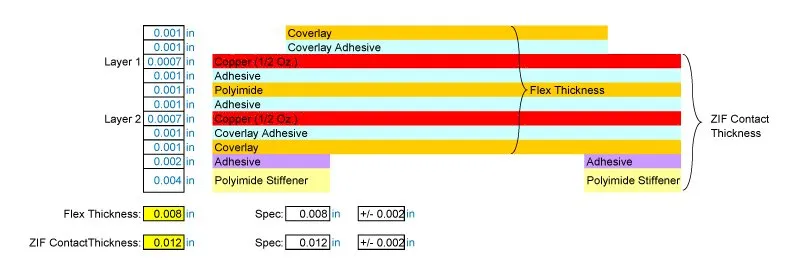
Adhesiveless laminates aid balance in high-flex designs. Engineer coverlay alignment to prevent asymmetry. These practices ensure mechanical stability throughout the lifecycle.
Related Reading: Flexible PCB Manufacturing Equipment: Handling Thin and Bendable Substrates
Insights from Production Environments
In factory settings, copper balancing reveals itself in yield metrics. Unbalanced flex panels often fail bend tests, showing cracks after 100,000 cycles. Balanced ones pass IPC flex endurance requirements consistently.
Troubleshooting starts with Gerber analysis for coverage maps. If imbalance exceeds 15 percent, redesign pours before tape-out. Thermal profiling during lamination confirms uniform cure.
Hybrid rigid-flex demands iterative prototyping. Initial runs expose curl in flex tails, resolved by adding dummy layers. Data logging from presses correlates pressure with flatness.
These insights drive scalable processes, minimizing variability.
Conclusion
Copper balancing stands as a cornerstone for flex PCB and rigid-flex PCB success, delivering superior PCB reliability and mechanical stability. By mitigating warpage and stress, it supports demanding applications while optimizing manufacturing. Electric engineers benefit from integrating it early in design, guided by proven practices. Prioritizing balance yields durable, high-performance boards ready for production.
FAQs
Q1: What is copper balancing in flex PCB design?
A1: Copper balancing involves achieving uniform copper density across layers in flex PCBs to prevent warpage during lamination and assembly. It uses symmetric trace routing and thieving patterns to equalize coverage, typically within 10 percent variance. This practice enhances PCB reliability by reducing thermal stresses and ensures mechanical stability for repeated bending. Factories verify it through coverage analysis and post-process metrology.
Q2: Why is copper balancing critical for rigid-flex PCB reliability?
A2: In rigid-flex PCBs, copper balancing prevents curling at flex-rigid transitions and maintains flatness in rigid sections. Imbalance causes differential shrinkage, leading to assembly defects and fatigue failures. Balanced designs improve PCB reliability under vibration and thermal cycles, aligning with IPC standards. It directly supports mechanical stability in compact, high-density applications.
Q3: How does copper balancing affect mechanical stability in flex PCBs?
A3: Copper balancing distributes stresses evenly, positioning the neutral axis centrally to minimize strain during flexing. This reduces microcrack risks in conductors and coverlay, enhancing long-term mechanical stability. Production benefits include higher bend cycle endurance and lower failure rates. Engineers achieve it via symmetric stackups and factory inspections.
Q4: What are common methods to implement copper balancing?
A4: Methods include copper thieving with grids or hatches in empty areas, symmetric layer pairing, and design rule checks for density. In manufacturing, panel-level balancing and lamination controls ensure uniformity. These steps boost PCB reliability without altering functionality, vital for flex and rigid-flex production.
References
IPC-2223E — Sectional Design Standard for Flexible/Rigid-Flexible Printed Boards. IPC, 2020
IPC-6013E — Qualification and Performance Specification for Flexible and Rigid-Flex Printed Boards. IPC, 2021