Introduction
Through-hole technology remains a cornerstone in printed circuit board assembly for applications demanding exceptional durability. In harsh environments characterized by intense vibration, extreme temperature fluctuations, and mechanical shocks, through-hole components provide unmatched reliability compared to surface-mount alternatives. Engineers designing for sectors like aerospace, automotive, and industrial equipment often prioritize through-hole design vibration resistance to ensure long-term performance. This approach leverages the inherent mechanical interlocking of component leads passing through plated holes and secured by solder fillets. As environmental stresses intensify, the rugged nature of through-hole assemblies becomes increasingly vital for mission-critical systems. Factory processes aligned with industry standards further enhance these benefits, making through-hole a strategic choice.
What Is Through-Hole Technology and Why It Matters in Harsh Environments
Through-hole technology involves inserting component leads into drilled holes on the PCB, followed by soldering on the opposite side to form robust connections. This contrasts with surface-mount technology, where components sit atop pads and rely solely on solder paste for attachment. In controlled settings, surface-mount offers density advantages, but harsh environments expose its vulnerabilities to fatigue from cyclic loading. Through-hole design temperature extremes tolerance stems from larger solder joints that accommodate thermal expansion differences between materials. Vibration and shock, common in off-road vehicles or turbine controls, amplify these disparities, where through-hole excels due to superior strain distribution. Factory-driven insights reveal that through-hole assemblies maintain integrity longer under combined stresses, justifying their use in high-reliability production.
The relevance escalates in industries facing regulatory scrutiny for uptime and safety. Automotive electronics, for instance, endure constant road vibrations alongside engine bay heat, demanding through-hole components ruggedized for such conditions. Similarly, oil and gas exploration gear operates amid corrosive atmospheres and seismic jolts, where failure equates to costly downtime. Standards like IPC-2221 guide designers in optimizing these features, ensuring boards meet performance thresholds. Procurement teams value this predictability, as through-hole reduces rework in volume manufacturing. Ultimately, selecting through-hole aligns engineering goals with real-world operational demands.
Technical Principles of Through-Hole Durability
The core strength of through-hole lies in its mechanical anchorage. Component leads extend fully through the board, creating a barrel-like structure reinforced by plating and solder. This configuration distributes forces across a greater surface area, resisting pull-out under vibration far better than surface-mount pads. In dynamic tests, through-hole joints exhibit minimal microcracking even after prolonged exposure to oscillatory loads. Factory experience confirms that proper plating thickness, per IPC guidelines, prevents barrel cracking from flexure. Through-hole design vibration resistance thus originates from this tri-dimensional fixation, unlike the planar bonds prone to peel-off in surface-mount.
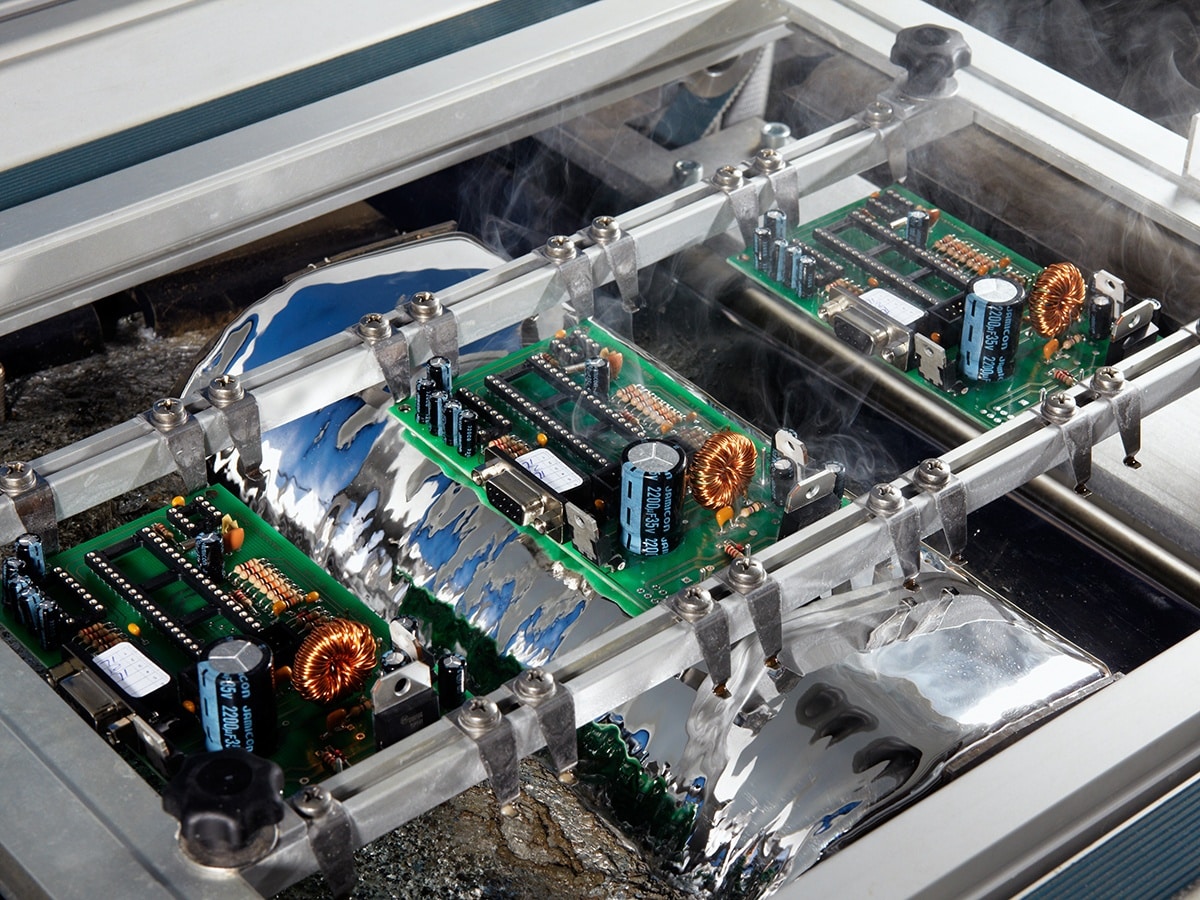
Temperature extremes challenge all assemblies through coefficient of thermal expansion mismatches. Through-hole solder fillets, being volumetric, flex without fracturing during rapid heating or cooling cycles. Leads act as compliant bridges, absorbing differential strains between components and the PCB substrate. This resilience suits environments swinging from sub-zero to over 100 degrees Celsius, common in avionics or downhole tools. JEDEC standards for thermal shock testing underscore how through-hole withstands such profiles without delamination. Enhanced heat dissipation via lead conduction further stabilizes hotspots, prolonging component life.
Ruggedization extends to component selection and joint geometry. Axial or radial leads in through-hole formats inherently possess higher mass and standoff, damping vibrations before they reach solder. Clinched leads, bent at 90 degrees within holes, boost retention force exponentially. Solder wicking up leads forms hourglass shapes that enhance fatigue resistance. These principles, rooted in material science, make through-hole components ruggedized for shock up to military specs. Manufacturing tolerances ensure consistent fillet heights, critical for thermal cycling endurance.
Environmental synergies amplify benefits. In humid or dusty settings, through-hole enclosures protect joints better than exposed surface-mount. Corrosion resistance improves with conformal coatings over protruding leads. Combined vibration and temperature accelerate failure modes like pad lifting in surface-mount, but through-hole mitigates via redundancy. Finite element analysis often models these interactions, validating empirical factory data. Overall, these mechanisms position through-hole as the default for unforgiving deployments.
Best Practices for Implementing Through-Hole in Harsh Designs
Designers start with hole sizing per IPC-2221, ensuring annular ring adequacy for plating integrity. Oversized holes risk weak barrels, while undersized complicate insertion; optimal ratios balance manufacturability and strength. Pad diameters should exceed hole by at least 0.4 mm for reliable fillets. Component lead diameters demand matching to avoid stress concentrations. Factory tooling verifies drill accuracy to prevent wander, a common vibration initiator. Through-hole design vibration resistance hinges on these foundational specs.
Material selection bolsters extremes tolerance. FR-4 with high Tg suits moderate heat, but polyimides excel in severe profiles. Plated through-hole copper thickness of 25 microns minimum guards against fatigue. Wave soldering parameters control ramp rates to minimize voids. Post-solder inspection per IPC-A-600 confirms fillet convexity, predictive of thermal reliability. Ruggedized through-hole components ruggedized feature tinned leads for oxidation resistance.
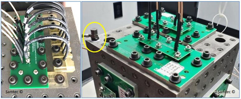
Assembly sequencing prevents damage. Pre-form leads to avoid board stress during insertion. Selective soldering for mixed tech preserves surface-mount viability. Vibration testing post-assembly simulates field use, iterating designs early. Conformal coating thickness uniformity protects against ingress. Documentation traces lots for traceability in failures.
Quality control integrates standards throughout. IPC-6012 qualification verifies class 3 compliance for harsh apps. Thermal profiling ensures peak exposures stay within component ratings. X-ray checks internal voids invisible externally. These steps yield defect rates under 100 ppm in high-volume runs. Engineers gain confidence through validated processes.
Real-World Applications and Insights
Aerospace actuators exemplify through-hole prowess. Constant g-forces and thermal swings demand unyielding joints; through-hole delivers without hybrid compromises. Industrial motor drives face grease, dust, and 80 Hz vibes; ruggedized electrolytics in through-hole slots endure. Factory retrofits often revert to through-hole for proven uptime. Troubleshooting reveals surface-mount fatigue first under combo stresses. Hybrid boards strategically place through-hole at stress points.
Oilfield sensors log millions of cycles in 150C heat. Through-hole thermistors maintain calibration where surface-mount drifts. Automotive ECUs prioritize through-hole power devices for surge handling. These cases affirm factory wisdom: match tech to threat profile.
Conclusion
Through-hole technology stands resilient in harsh environments through mechanical superiority and thermal forgiveness. Its vibration resistance, temperature endurance, and ruggedized adaptability address engineering pain points effectively. Standards-guided design and factory rigor unlock these advantages consistently. For electric engineers tackling demanding specs, through-hole remains indispensable. Future hybrids may evolve, but core principles endure.
FAQs
Q1: How does through-hole design vibration resistance outperform surface-mount in dynamic applications?
A1: Through-hole leads anchor deeply into plated barrels, distributing vibrational energy across larger volumes than surface-mount pads. Solder fillets provide compliance, reducing shear stress at interfaces. Factory tests show through-hole joints surviving 10x cycles before microcrack initiation. This makes it ideal for engines or machinery. Standards like IPC-2221 optimize geometries for peak performance.
Q2: What enables through-hole design temperature extremes handling?
A2: Volumetric joints in through-hole flex with CTE mismatches, unlike brittle surface-mount fillets. Leads conduct heat away, stabilizing junctions during cycles. JEDEC thermal shock protocols confirm superior survival rates. Ruggedized components extend operational windows in avionics or geothermal gear. Factory soldering controls minimize voids for reliability.
Q3: Why choose through-hole components ruggedized for high-reliability boards?
A3: Ruggedized through-hole offers standoff and mass damping shocks effectively. Mechanical interlock resists pull-out under loads. IPC-6012 class 3 qualification ensures harsh suitability. Applications like defense electronics benefit from repairability. Cost per cycle favors longevity in volume.
Q4: Can through-hole integrate with modern high-density designs?
A4: Yes, hybrids place through-hole at high-stress nodes while surface-mount fills elsewhere. Design rules per IPC standards prevent interference. Factories handle mixed assembly seamlessly. This balances density with through-hole design vibration resistance. Vibration and thermal margins improve overall board life.
References
IPC-2221B — Generic Standard on Printed Board Design. IPC, 2012
IPC-6012DS — Qualification and Performance Specification for Rigid Printed Boards in Space Applications. IPC, 2015
IPC/JEDEC J-STD-020E — Moisture/Reflow Sensitivity Classification for Nonhermetic Surface Mount Devices. JEDEC, 2014


