Introduction
Rigid-flex PCBs integrate rigid and flexible substrates into a single board, enabling compact designs in demanding applications like medical devices, aerospace systems, and wearable electronics. These boards offer superior reliability in dynamic environments compared to separate rigid and flex assemblies, but they come with higher production expenses due to specialized materials and processes. Engineers focused on rigid-flex PCB cost optimization must balance performance needs with economic constraints to achieve viable rigid-flex PCB ROI. Material choices and manufacturing steps represent the largest cost contributors, often accounting for significant portions of the total budget. By understanding these elements, designers can implement strategies that reduce rigid-flex PCB pricing without compromising functionality. This guide provides structured insights into optimizing materials and processes for cost-effective outcomes.
What Are Rigid-Flex PCBs and Why Cost Optimization Matters
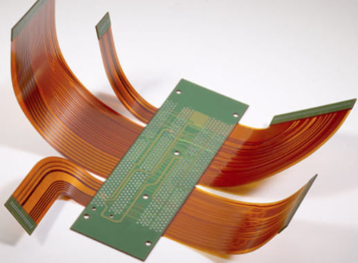
Rigid-flex PCBs combine rigid sections, typically made from epoxy-based laminates, with flexible sections using polyimide films, allowing the board to bend and fold during assembly or operation. This hybrid construction eliminates connectors and wiring harnesses, reducing assembly time and potential failure points in space-constrained products. In industries requiring high reliability, such as avionics or implantable devices, rigid-flex designs excel by maintaining signal integrity under mechanical stress. However, rigid-flex PCB manufacturing costs exceed those of standard rigid boards by factors tied to material premiums and process complexity. Without targeted rigid-flex PCB design for cost, projects risk inflated budgets that erode rigid-flex PCB ROI through extended development cycles or yield losses. Optimizing early in the design phase ensures competitiveness while meeting performance specifications.
The relevance of cost control grows with production volume, as economies of scale apply unevenly to rigid-flex due to specialized tooling. Engineers must evaluate total ownership costs, including testing and rework, to quantify true value. Proactive optimization aligns design choices with fabrication capabilities, minimizing iterations.
Key Factors Influencing Rigid-Flex PCB Material Costs
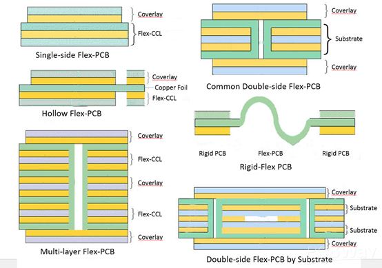
Material selection drives a substantial portion of rigid-flex PCB material costs, with flexible substrates like polyimide costing several times more than standard rigid laminates due to their thermal stability and ductility. Coverlay films protect flexible traces, while adhesives bond layers, but adhesiveless laminates reduce thickness and potential delamination risks at a moderate premium. Rigid sections rely on cost-effective FR4 cores and prepregs, yet matching coefficients of thermal expansion between rigid and flex areas prevents stress concentrations. Thinner copper foils in flex regions lower material expenses but require precise etching control to avoid defects. Minimizing the flex area's footprint, such as limiting it to signal paths only, directly cuts polyimide usage and thus rigid-flex PCB pricing.
Designers should specify materials based on environmental demands, opting for standard thicknesses where possible to leverage supplier inventories. Over-specifying high-end polyimides for non-critical sections inflates costs unnecessarily. Balancing dielectric properties with affordability ensures signal performance without excess expenditure.
Compliance with IPC-6013 qualification standards verifies material performance under flexure and thermal cycling, guiding selections that avoid costly requalifications.
Manufacturing Processes and Rigid-Flex PCB Manufacturing Costs
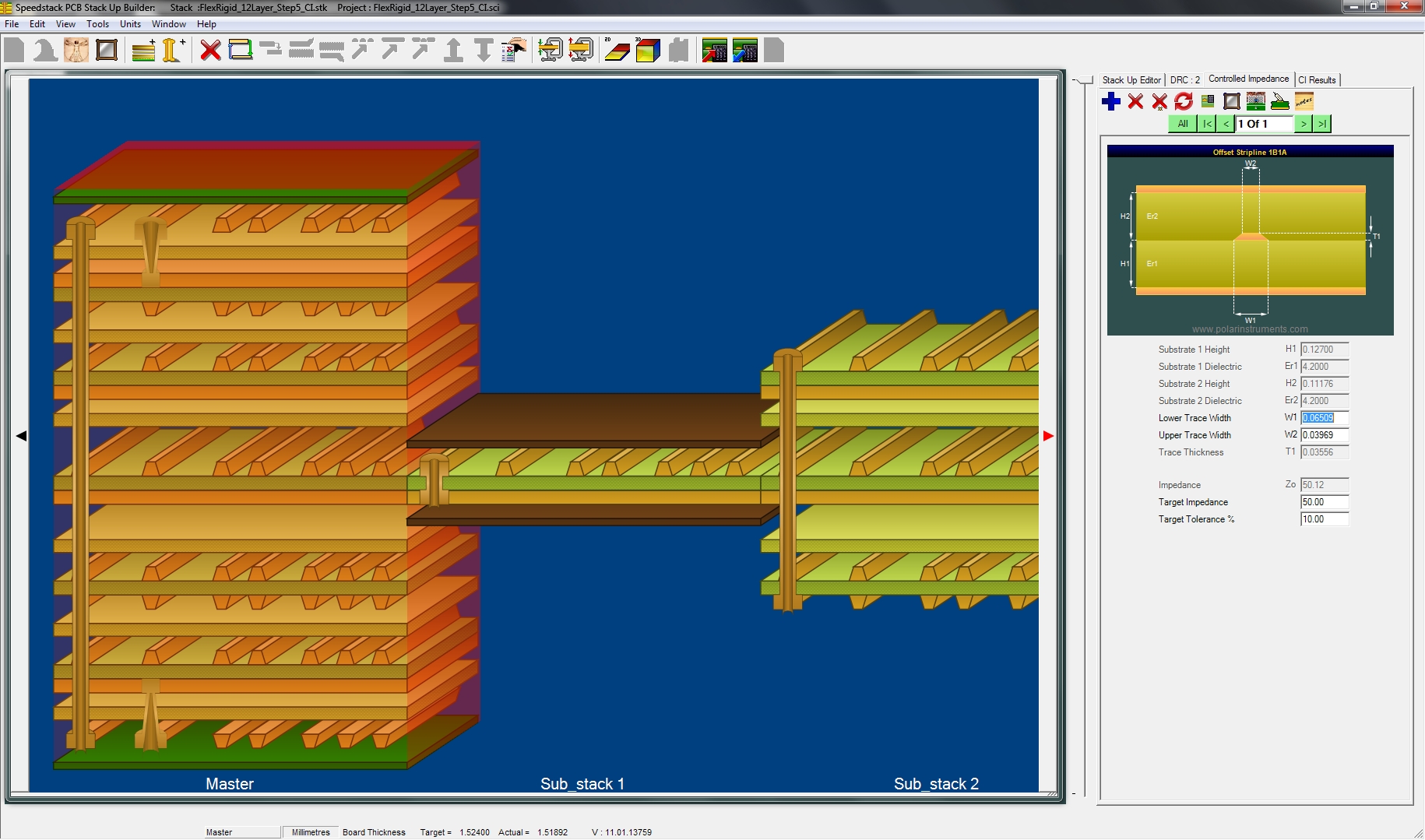
Rigid-flex fabrication involves sequential lamination, where rigid and flex cores build incrementally to align layers precisely, a process far more labor-intensive than single-lamination rigid boards. Laser drilling forms blind and buried vias in flex sections, essential for density but adding setup and cycle times that elevate rigid-flex PCB manufacturing costs. Controlled depth milling outlines flex tails, while coverlay application demands registration accuracy to prevent misalignment. Multiple press cycles for hybrid stackups increase handling risks and equipment wear, compounding expenses. Yield losses from warpage or adhesion failures during lamination further impact economics, emphasizing the need for design predictability.
Streamlining to fewer lamination steps, such as using pre-etched flex cores, reduces process iterations and tooling costs. Volume production amortizes setups, but prototypes suffer higher per-unit rigid-flex PCB pricing due to non-recurring engineering.
Adhering to IPC-2223 design guidelines during layout mitigates manufacturing pitfalls like excessive flex bends that complicate processing.
Design Best Practices for Rigid-Flex PCB Design for Cost
Effective rigid-flex PCB design for cost starts with stackup planning, minimizing flex layers and transitions to simplify lamination and lower material use. Position high-density components on rigid areas to avoid stress on flex traces, and incorporate strain-relief features like teardrop vias and curved bends with radii at least six times the copper thickness. Route wider traces in flex zones to enhance reliability and reduce etching precision needs, while panelizing multiple boards maximizes panel yield. Standardize outline dimensions and hole sizes to utilize existing tooling, cutting non-recurring costs. Simulate mechanical flexure early to identify warpage risks, preventing expensive prototypes.
Layer pairing in rigid sections optimizes impedance matching without extra grounds, preserving signal quality economically. Avoid buried vias in flex unless critical, favoring through-hole where feasible for simpler drilling.
These practices collectively enhance rigid-flex PCB cost optimization by aligning design intent with fabrication realities.
Strategies to Maximize Rigid-Flex PCB ROI
Rigid-flex PCB ROI emerges from lifecycle savings, including reduced assembly labor via integrated form factors and fewer field failures from connector elimination. Quantify pricing by factoring board size, layer count, flex length, and via density against volume forecasts. Partnering with fabricators for design reviews uncovers hidden costs like impedance test points or fiducials. Transitioning from prototypes to production via pilot runs refines yields, amplifying returns. Long-term, reliable designs lower warranty claims, boosting overall project economics.
Investing in design optimization upfront yields compounding benefits, as mature layouts scale efficiently.
Conclusion
Optimizing rigid-flex PCB cost is a strategic balancing act between cutting-edge engineering and fiscal responsibility. While the initial investment in rigid-flex PCB manufacturing costs may be higher than traditional alternatives, the long-term rigid-flex PCB ROI is realized through reduced assembly complexity, enhanced signal integrity, and superior mechanical reliability. By prioritizing early-stage design for cost (DfC), selecting materials that align with environmental demands, and adhering to IPC standards, engineers can significantly lower rigid-flex PCB pricing without sacrificing performance. Ultimately, successful cost optimization transforms these complex components from a luxury high-end solution into a viable, scalable technology for modern, space-constrained electronics.


