Introduction
High-speed PCB design demands precise control over signal propagation to maintain integrity across rising data rates and frequencies. The choice of dielectric material fundamentally influences performance by determining how signals travel through the board. Engineers must evaluate high-speed PCB materials based on their electrical properties to minimize losses and distortions. Key factors like dielectric constant and loss tangent guide material selection for optimal high-frequency performance. This article explores these principles, common options, and strategies for effective implementation. Understanding these elements ensures reliable designs in demanding applications.
Understanding Dielectrics in High-Speed PCB Design
Dielectrics serve as the insulating core in printed circuit boards, separating conductive layers and supporting signal transmission. In high-speed contexts, the dielectric's interaction with electromagnetic fields becomes critical for preserving waveform fidelity. Materials with stable properties reduce variations in signal delay and attenuation. Poor choices lead to issues like impedance mismatches and crosstalk, compromising overall system reliability. Engineers prioritize dielectrics that support controlled impedance traces typical in modern designs. This foundation enables scaling to higher frequencies without excessive redesign.
The relevance stems from increasing clock speeds in processors, memory interfaces, and RF systems. Traditional materials suffice for lower speeds but falter at gigahertz ranges due to inherent losses. High-speed PCB materials address these by offering tailored dielectric behaviors. Material selection thus aligns with specific frequency bands and loss budgets. Compliance with standards like IPC-4101 ensures consistency in qualification and performance.
Key Electrical Properties of Dielectric Materials
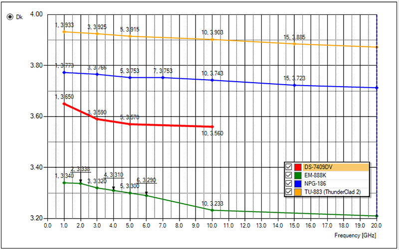
Dielectric constant, often denoted as Dk or εr, quantifies a material's ability to store electrical energy relative to air. Lower values accelerate signal propagation, reducing propagation delay in traces. Stability across frequencies prevents timing skew in differential pairs. Variations with temperature or humidity can degrade performance, so engineers seek materials with minimal fluctuation.
Loss tangent, or Df, measures energy dissipation as heat during signal transit. Lower Df preserves signal amplitude, crucial for long traces or high bit rates. It directly impacts insertion loss, where higher values attenuate high-frequency components. Combined with conductor losses, Df determines overall channel performance. Testing per IPC-TM-650 methods verifies these properties under realistic conditions.
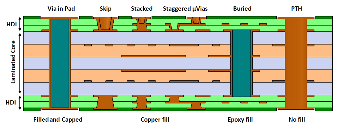
Other factors include coefficient of thermal expansion (CTE) for mechanical reliability and moisture absorption for environmental stability. High CTE mismatch causes warpage during assembly. Low absorption prevents Dk shifts in humid environments. These properties interplay in multilayer stacks, influencing via integrity and board flatness.
Common Dielectric Materials for High-Speed Applications
FR-4 remains the baseline for many designs, offering cost-effective epoxy-glass reinforcement with moderate dielectric constant around 4.0 to 4.7. Its loss tangent suits frequencies up to several hundred megahertz but rises at gigahertz levels, limiting high-frequency performance. Signal integrity suffers from increased attenuation and dispersion in longer runs. Despite these constraints, FR-4 dominates due to availability and process compatibility.
For superior high-speed PCB materials, polytetrafluoroethylene (PTFE)-based dielectrics excel with lower dielectric constant near 2.0 to 3.0 and minimal loss tangent below 0.001. These support microwave and mmWave applications by minimizing dielectric losses. Ceramic or glass-filled PTFE variants enhance rigidity and thermal conductivity. However, PTFE poses fabrication challenges like higher CTE and drill smear.
Hybrid materials blend FR-4 with low-loss cores for balanced performance. Hydrocarbon ceramics provide low Dk stability without PTFE drawbacks. Each category trades cost, machinability, and electrical traits. Engineers compare datasheets focusing on target frequencies and stackup needs.
- FR-4 — Typical use case: Low to mid-speed digital; Strengths: Cost, availability; Considerations: Higher losses at GHz.
- PTFE-based — Typical use case: RF, high-frequency; Strengths: Low Dk/Df; Considerations: Fabrication complexity.
- Ceramic-filled — Typical use case: High-speed mixed-signal; Strengths: Stability, low loss; Considerations: Cost premium.
Impact of Dielectric Choice on Signal Integrity
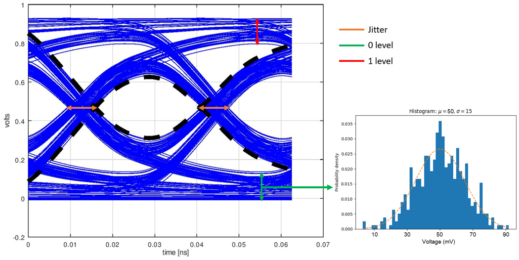
Signal integrity hinges on controlled propagation velocity and minimal attenuation. Dielectric constant sets the effective index, where higher Dk slows signals, complicating length matching. In stripline or microstrip configurations, Dk uniformity avoids intra-pair skew. Simulations reveal how material variations amplify eye closure at data rates above 10 Gbps.
Loss tangent contributes to frequency-dependent loss, eroding high-frequency harmonics. This manifests as intersymbol interference and jitter. Conductor surface roughness compounds dielectric losses, emphasizing low-profile copper pairs. Crosstalk rises with higher Dk due to stronger capacitive coupling. Proper material selection maintains return loss below -20 dB across bands.
At multi-gigabit speeds, dielectric absorption causes baseline wander. Low-loss materials mitigate this, preserving eye height. Thermal effects alter Dk, shifting impedance during operation. High-speed designs thus incorporate margin for these dynamics.
Best Practices for Material Selection in High-Speed Designs
Begin with frequency and loss budget analysis to narrow options. Define rise times and trace lengths to estimate required Dk and Df thresholds. Consult supplier data for frequency-swept properties. Prioritize IPC-6012 qualified materials for qualification assurance.
Stackup design integrates dielectric thickness for 50-ohm impedance. Thinner cores demand lower Dk to avoid tight tolerances. Simulate full channels including vias and bends. Prototype testing validates models, measuring S-parameters for correlation.
Fabrication compatibility guides final choice. PTFE requires specialized drilling and plating to avoid inconsistencies. Cost-benefit weighs performance gains against premiums. Collaborate early with manufacturers for DFM feedback.
Challenges and Mitigation Strategies
High-speed materials introduce warpage from CTE mismatches in hybrids. Sequential lamination controls this, building layers incrementally. Vias in low-Dk materials risk stub resonance; blind or buried types minimize impact.
Moisture sensitivity alters properties; bake-out prevents issues. Lead-free assembly demands higher Tg for reliability. Troubleshooting involves TDR for impedance profiles and VNA for losses.
Conclusion
Selecting the right dielectric underpins high-speed PCB success by optimizing dielectric constant, loss tangent, and ancillary properties. FR-4 suits general use, while PTFE and hybrids elevate high-frequency performance. Signal integrity benefits from low-loss choices, guided by systematic evaluation. Adhering to best practices ensures manufacturability and reliability. Engineers achieve robust designs by balancing electrical, mechanical, and economic factors.
FAQs
Q1: What is the dielectric constant and why does it matter for high-speed PCB materials?
A1: The dielectric constant (Dk) indicates how much a material slows electromagnetic waves compared to vacuum. In high-speed designs, lower Dk reduces propagation delay, aiding timing alignment in high-frequency signals. Variations cause skew, degrading signal integrity. Stable Dk across temperature ensures consistent performance. Material selection focuses on Dk suited to operating frequencies.
Q2: How does loss tangent affect high-frequency performance in PCBs?
A2: Loss tangent (Df) quantifies signal energy converted to heat in the dielectric. Lower Df minimizes attenuation, preserving amplitude at high frequencies. It dominates losses beyond a few GHz, impacting eye diagrams. High-speed PCB materials with Df under 0.005 excel in long channels. Testing verifies Df for specific bands.
Q3: When should engineers choose PTFE over FR-4 for signal integrity?
A3: PTFE offers superior low loss tangent and dielectric constant for RF and multi-Gbps digital. FR-4 limits arise above 1 GHz due to rising losses. Select PTFE for stringent high-frequency performance needs, accepting higher costs. Hybrids bridge gaps for mixed applications.
Q4: What role do standards play in high-speed PCB material selection?
A4: Standards like IPC-4101 define material specs for consistency. IPC-TM-650 provides test methods for Dk and Df verification. They ensure qualification for reliability. Compliance aids procurement and reduces risks.
References
IPC-4101E — Specification for Base Materials for Rigid and Multilayer Printed Boards. IPC, 2017
IPC-TM-650 2.5.5.3 — Test Methods Manual: Dielectric Constant (Permittivity). IPC, 2020
IPC-6012E — Qualification and Performance Specification for Rigid Printed Boards. IPC, 2017


