Introduction
PCB breakaway rails play a critical role in modern electronics manufacturing, particularly for high-volume surface-mount technology (SMT) production. These rails allow multiple individual boards to be processed as a single panel, improving efficiency during automated assembly lines. By providing structural support and precise alignment features, breakaway rails minimize handling damage and ensure consistent placement of components. Electrical engineers designing for manufacturability must understand PCB breakaway rails design to optimize panelization strategies. This guide explores the engineering principles, best practices, and troubleshooting tips for implementing breakaway rails effectively. Ultimately, proper design enhances stability during reflow soldering and streamlines depanelization post-assembly.
What Are PCB Breakaway Rails and Why Do They Matter?
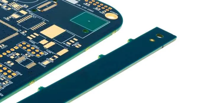
PCB breakaway rails, also known as edge rails or process edges, are extended strips attached to the perimeter of a panelized array of printed circuit boards. They facilitate secure handling by SMT equipment, such as pick-and-place machines and reflow ovens, which rely on standardized conveyor systems. Without these rails, individual small boards risk misalignment, warpage, or falling during high-speed processing. Breakaway rails are perforated or scored for easy separation after assembly, preserving the integrity of the final boards. Their importance grows with miniaturization trends, where panel efficiency directly impacts yield and cost.
In high-mix, low-volume production, breakaway rails enable economies of scale by maximizing panel utilization. They accommodate essential features like tooling holes and fiducials, which are vital for machine vision alignment. Engineers overlook them at their peril, as poor rail design leads to assembly rejects or mechanical stress fractures. Adhering to established design principles ensures compliance with quality benchmarks, reducing downstream issues in testing and packaging.
Core Principles of PCB Breakaway Rails Design
Effective PCB breakaway rails design begins with understanding load distribution and mechanical stability during thermal cycling. Rails must withstand conveyor friction, vibrational stresses from handlers, and expansion mismatches between the panel and assembly fixtures. Material continuity from the base laminate extends into the rails, maintaining planarity to prevent board sagging in reflow ovens. Design considerations include rail orientation, typically along the two longest edges of the panel for optimal machine compatibility. Asymmetric layouts can introduce torque, compromising placement accuracy.
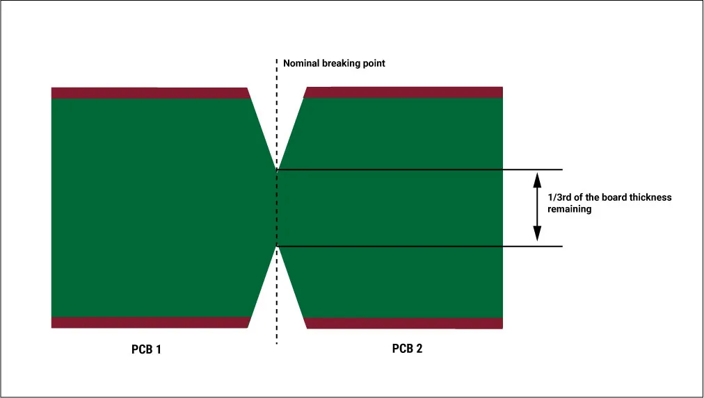
Breakaway mechanisms, such as perforated tabs or v-scoring, define the separation interface. Perforations consist of alternating drilled holes and webs, with hole diameters and spacings engineered to balance strength and ease of depaneling. V-scoring uses partial-depth cuts from both sides, meeting at the midline for clean breaks. These features must align with the panel's overall rigidity, avoiding stress concentrations near sensitive components. Logical placement ensures uniform force application during manual or automated singulation.
Optimizing Breakaway Rail Dimensions
Breakaway rail dimensions directly influence panel handling and equipment throughput. Common rail widths range from 5 mm to 10 mm, providing sufficient space for tooling features while minimizing material waste. Narrower rails below 5 mm risk instability under conveyor loads, whereas wider ones up to 10 mm offer enhanced support for larger panels. Engineers select dimensions based on panel size, board count, and machine specifications, ensuring rails extend fully across transport edges. Dimensional consistency prevents jams in automated lines, where tolerances as tight as 0.1 mm matter.
Thickness matches the core PCB stack-up, typically 1.6 mm for standard FR-4 panels, to avoid differential warpage. Rails should incorporate copper balancing if the array has varying densities, promoting flatness per IPC-2221 design guidelines. Overly thin or irregular dimensions amplify thermal gradients, leading to solder joint defects. By standardizing these parameters early, designers streamline transitions from prototyping to volume production.
Fiducial Placement in Breakaway Rails
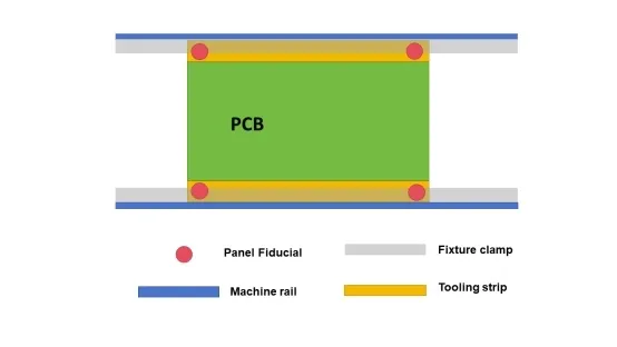
Fiducial placement breakaway rails is essential for precision alignment in vision-guided SMT systems. Fiducials are bare copper pads, typically 1-2 mm in diameter, etched to high contrast against the solder mask. Position them at the panel's diagonal corners on the rails, at least 5 mm from any edge to avoid occlusion by fixtures. Global fiducials reference the entire panel, while local ones on individual boards fine-tune per-board placement. Asymmetry in placement, such as equal distances from corners, aids machine algorithms in distinguishing rotation from translation errors.
Optimal fiducial design includes a clear zone of 3 mm radius free of silkscreen or components. Place at least three per panel, with a fourth for redundancy in high-precision applications. Rail integration keeps fiducials away from board arrays, reducing contamination risks during handling. Proper fiducial placement breakaway rails ensures sub-0.05 mm repeatability, critical for fine-pitch BGA components.
Tooling Holes in Breakaway Rails
Tooling holes breakaway rails secure the panel against pins in feeders and indexers. These non-plated holes, commonly 3.2 mm in diameter, are spaced according to machine pitch, often 50 mm apart along the rail centerline. Placement centers them midway on the rail width, with at least 5 mm clearance to perforations or fiducials. Multiple holes, typically four per long edge, distribute loads evenly and accommodate varying panel lengths. Oversized or undersized holes lead to slippage, misregistration, or pin wear.
Drill tolerances hold to ±0.1 mm for reliability, with chamfers preventing burrs that snag conveyors. Tooling holes breakaway rails must avoid proximity to v-scores, maintaining at least 10 mm separation to preserve structural margins. In dual-rail designs, symmetrize placement for bidirectional processing. This setup complies with assembly process controls, enhancing overall line uptime.
Best Practices for SMT Assembly with Breakaway Rails
SMT assembly with breakaway rails demands coordinated design and process parameters. Begin with panel layout optimization, arranging boards in a grid that maximizes yield while fitting standard carrier sizes. Rails on opposing edges enable conveyor transport, with fiducials calibrated during setup. Pre-bake panels to mitigate moisture per JEDEC guidelines, preventing popcorn effects that warp rails. Stencil alignment leverages rail fiducials for uniform paste deposition across the array.
During reflow, monitor rail temperatures with thermocouples to validate profiles. Post-print inspection scans the entire panel, flagging defects before placement. Pick-and-place sequences prioritize rail stability, using vacuum nests if needed. After soldering, inline AOI confirms joint quality without depaneling. These steps, aligned with IPC J-STD-001 requirements, minimize escapes to final test.
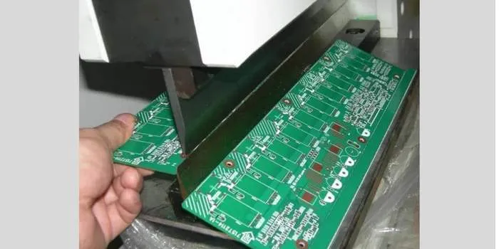
Depaneling follows cooling, using routers or shears matched to breakaway features. Guillotine presses work for v-scored rails, applying force perpendicular to scores. Inspect singulated boards for chipping or microcracks along edges. Automated systems with vision feedback further reduce variability.
Troubleshooting Common Issues with Breakaway Rails
Rail warpage manifests as bowing during reflow, often from asymmetric copper distribution. Balance layers across the panel, extending ground planes into rails judiciously. Measure flatness with straightedges or laser gauges pre-assembly. If persistent, adjust stack-up thickness or incorporate stiffeners.
Misalignment in fiducials stems from etch tolerances or mask registration errors. Verify Gerber offsets and simulate vision detection. Relocate if shadowed by components. Tooling hole wear causes drift; inspect pins regularly and replate holes if elongated.
Depaneling damage, like burrs or delamination, arises from dull tools or excessive force. Hone router bits and sequence cuts from periphery inward. For tabs, ensure web thickness exceeds 0.4 mm for clean breaks. Post-depanel x-rays detect subsurface cracks.
Conclusion
Mastering PCB breakaway rails design transforms assembly challenges into efficiency gains. From precise breakaway rail dimensions to strategic fiducial placement breakaway rails and tooling holes breakaway rails, each element contributes to robust SMT assembly with breakaway rails. Engineers achieve higher yields by integrating these principles logically into the design flow. Standards like IPC-2221 and IPC J-STD-001 provide foundational guidance, ensuring reliability across production scales. Prioritize simulation and DFM reviews to preempt issues. With disciplined implementation, breakaway rails elevate product quality and accelerate time-to-market.
FAQs
Q1: What are standard breakaway rail dimensions for SMT panels?
A1: Breakaway rail dimensions typically range from 5 mm to 10 mm in width to support conveyor handling and feature integration. Select based on panel size and machine requirements, ensuring at least 3 mm minimum for stability. This accommodates tooling holes breakaway rails and fiducials without compromising rigidity. Proper sizing per design guidelines prevents warpage and alignment errors during PCB breakaway rails design.
Q2: How should fiducial placement breakaway rails be optimized?
A2: Position fiducials on breakaway rails at panel corners, 5 mm from edges, using 1-2 mm copper pads with clear zones. Include three or more for global alignment in SMT machines. Avoid heavy copper areas to maintain contrast. This fiducial placement breakaway rails ensures precise component placement across the array.
Q3: Why are tooling holes breakaway rails critical for assembly?
A3: Tooling holes breakaway rails, around 3.2 mm diameter, secure panels on pins for accurate indexing. Space them evenly along rails, away from scores. They enable repeatable positioning in pick-and-place and reflow. Neglect leads to shifts, impacting SMT assembly with breakaway rails quality.
Q4: What best practices improve SMT assembly with breakaway rails?
A4: Optimize panel layout with balanced rails, calibrate fiducials, and validate reflow profiles. Use perforations or v-scoring for clean depaneling. Monitor for warpage and burrs. These steps in SMT assembly with breakaway rails boost yields and comply with assembly standards.
References
IPC-2221 — Generic Standard on Printed Board Design. IPC, 2012
IPC J-STD-001G — Requirements for Soldered Electrical and Electronic Assemblies. IPC, 2017
IPC-A-610H — Acceptability of Electronic Assemblies. IPC, 2019