Introduction
In high-density PCB designs, via-in-pad structures offer a compact solution by placing vias directly within component pads, maximizing routing space under fine-pitch devices like BGAs. This approach supports HDI PCB design where real estate is at a premium, enabling tighter layouts and shorter signal paths. However, via-in-pad introduces fabrication challenges such as filling requirements and potential reliability concerns during assembly. Engineers often evaluate PCB via alternatives like blind vias, buried vias, and microvias to balance density, cost, and performance. Selecting the right via structure depends on layer count, signal integrity needs, and manufacturing capabilities. This article explores when to opt for these alternatives over via-in-pad, providing structured guidance for electric engineers.
Understanding Via-in-Pad Structures
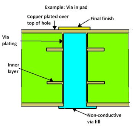
Via-in-pad, also known as via-in-pad or VIP, involves drilling a via hole directly into a surface pad, plating it, and then filling it with conductive or non-conductive material before capping with solder mask or metal. This eliminates the need for separate annular rings around the via, freeing up surface area for components. In HDI PCB design, it proves essential for fanout from high-I/O count packages, reducing trace lengths and inductance. The process demands precise control during plating to avoid voids, followed by planarization to ensure flatness for soldering. While effective, the added steps increase lead times and costs compared to standard through-hole vias. Engineers must weigh these factors against design density goals.
Limitations of Via-in-Pad in Modern Designs
Fabrication of via-in-pad requires specialized processes like electroplating fill or epoxy plug, which can lead to inconsistencies if not managed properly. Potential issues include incomplete filling causing solder wicking during reflow or trapped air pockets that compromise thermal performance. In multilayer boards, coefficient of thermal expansion mismatches between fill material and copper may induce stress cracks over thermal cycles. Reliability testing reveals that uncapped or poorly filled vias risk contamination or delamination under humidity exposure. For designs exceeding certain densities, these risks prompt consideration of PCB via alternatives that avoid surface exposure altogether. Cost escalation from multiple lamination cycles further influences the decision to explore blind vias or buried vias.
Core Via Types and Their Roles
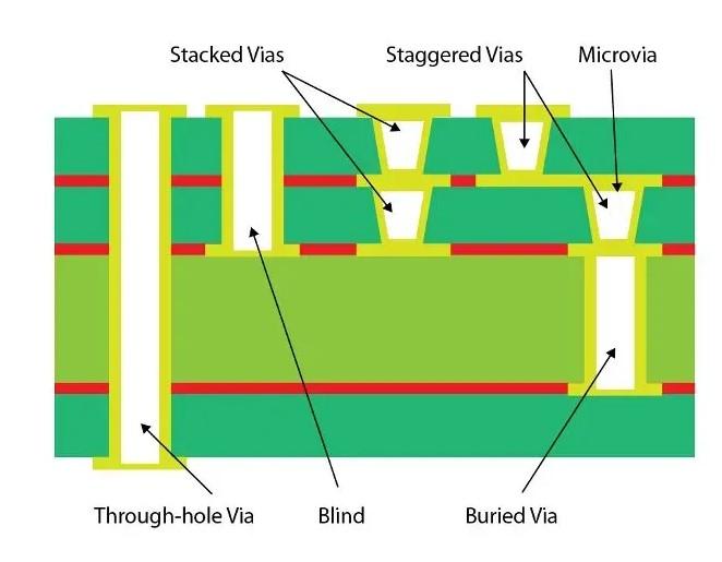
PCBs employ several via configurations, each suited to specific interconnect needs. Through-hole vias span the entire board thickness, offering simplicity but consuming pads on both surfaces. Blind vias connect an outer layer to one or more inner layers without penetrating to the opposite side, preserving surface space on the unused exterior. Buried vias link only internal layers, invisible from surfaces and ideal for dense inner routing. Microvias, typically laser-drilled with diameters under 150 microns, function as miniaturized blind or buried vias in HDI applications. Understanding these distinctions guides selection based on stackup complexity and impedance control.
Blind Vias: Targeted Outer-to-Inner Connections
Blind vias start from a surface pad and terminate at an inner layer, enabling efficient layer transitions without full board penetration. They reduce stub inductance compared to through-hole vias, benefiting high-speed signals by minimizing reflections. In designs with 8-12 layers, blind vias support fanout from surface components while freeing the bottom side for other uses. Fabrication involves sequential lamination, where outer layers build around pre-drilled inner structures. Per IPC-2226 guidelines for HDI PCB design, blind via aspect ratios should stay below 1:1 for reliable plating. Choose blind vias when connecting top-layer traces to layer 2 or 3, avoiding the complexity of full via-in-pad filling.
Engineers specify blind vias for applications like RF modules where signal integrity demands short vias. The structure allows smaller pad sizes on the surface, aiding density without via-in-pad's capping needs. However, drill depth control proves critical to prevent breakthroughs. Combining blind vias with filled via-in-pad on select nets optimizes hybrid layouts. Overall, they offer a reliable PCB via alternative for moderate HDI needs.
Buried Vias: Invisible Inner Layer Interconnects
Buried vias reside entirely within the core, connecting inner signal or power planes without surface access. This eliminates surface pad real estate usage, maximizing component mounting area. Ideal for multilayer boards over 12 layers, buried vias facilitate plane-to-plane transitions with low capacitance. During build-up, they form via sequential lamination cycles, aligning with IPC-6012 specifications for rigid board performance. Their complete encapsulation shields against environmental factors, enhancing long-term reliability. Opt for buried vias in designs prioritizing inner density over surface vias.
The absence of surface stubs improves crosstalk isolation, crucial for parallel high-speed buses. Fabrication costs rise with additional imaging steps, but savings accrue from reduced surface clutter. Engineers pair buried vias with blind structures for comprehensive HDI stackups. Aspect ratio limits mirror blind vias, ensuring plating uniformity. As a PCB via alternative, buried vias excel when via-in-pad proves too costly for non-surface nets.
Microvias: Enabling Ultra-High Density
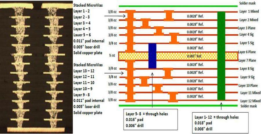
Microvias represent the pinnacle of miniaturization, with laser-drilled apertures typically 50-150 microns, enabling connections spanning one or two layers. Stacked microvias build vertically for deeper reaches, while staggered configurations offset for fanout efficiency. In HDI PCB design, they support 0.3mm pitch BGAs impossible with mechanical drills. IPC-2226 defines microvia parameters, emphasizing dielectric control for via reliability. Their small size reduces inductance dramatically, suiting 5G and computing applications. Select microvias over via-in-pad when pitch constraints demand sub-100 micron features.
Reliability hinges on photo-defined dielectrics and precise laser ablation to avoid resin smear. Elastomeric fills enhance CTE matching in stacked arrays. Manufacturing involves multiple build-up cycles, increasing complexity but yielding densities up to 1.5x standard multilayers. As PCB via alternatives, microvias transform space-limited designs. Blind and buried microvias further optimize by hiding connections.
When to Choose PCB Via Alternatives Over Via-in-Pad
Transition from via-in-pad when fabrication yields drop below 95% or costs exceed budget thresholds. For 4-8 layer boards, blind vias suffice for outer fanout, avoiding fill processes. Buried vias suit inner power distribution in 10+ layer stackups, per IPC-6012 quality classes. Microvias become mandatory for HDI types II/III with fine-pitch escapes. Evaluate signal speed: shorter blind/micro vias cut via resonance below 10 GHz. Layer count dictates: low layers favor blind, high layers leverage buried/micro combinations.
Hybrid approaches mix via types: via-in-pad for critical BGAs, blind elsewhere. Simulate impedance pre-layout to confirm choices. Cost models factor lamination cycles: one cycle for blind, multiple for buried/micro. Reliability data from thermal cycling guides final selection. These PCB via alternatives enhance design margins without density loss.
Best Practices for Implementing Via Alternatives in HDI PCB Design
Adhere to aspect ratios under 1:1 for blind and microvias to ensure void-free plating. Oversize pads by at least 150 microns over drill diameter for capture alignment. Sequence lamination carefully, building from core outward for buried integration. Employ laser drilling for microvias to achieve taper-free walls. Verify stackup symmetry to mitigate warpage. Test via chain continuity post-fab.
Route signals away from via clusters to distribute stress. Use filled microvias under pads only if planarized. Simulate thermal profiles for CTE compatibility. Document via types in fab drawings for DFM review. These practices align with industry standards, ensuring robust HDI outcomes.
Real-World Design Considerations
Consider a 12-layer server board with 0.4mm BGA: initial via-in-pad raised costs 30% due to copper fill. Switching to blind microvias on outer layers and buried for inners cut cycles while maintaining density. Signal integrity improved with 20% shorter paths. Another case involved automotive electronics: buried vias isolated power planes, blind vias handled GPIO escapes, avoiding via-in-pad thermal risks. These shifts highlight practical PCB via alternatives tailoring.
Conclusion
Via-in-pad excels in extreme density but falters under cost and reliability pressures, prompting blind vias, buried vias, or microvias as superior PCB via alternatives. Blind structures suit surface-to-inner links, buried for internal routing, and microvias for HDI PCB design pinnacles. Logical selection based on layers, speed, and fab hinges on standards like IPC-2226. Engineers gain optimized boards by matching via types to needs, enhancing performance without compromise. Prioritize simulations and DFM for success.
FAQs
Q1: What are the main PCB via alternatives to via-in-pad?
A1: Blind vias connect outer to inner layers, buried vias link internals only, and microvias provide miniaturized versions for HDI PCB design. Choose based on space: blind for surface efficiency, buried for hidden density, microvias for fine pitch. These reduce filling needs and costs while maintaining integrity.
Q2: When should electric engineers use blind vias over via-in-pad?
A2: Opt for blind vias in moderate multilayer boards needing outer-to-layer 2/3 connections, avoiding via-in-pad's fill and cap processes. They offer better inductance control for high-speed signals without full penetration. Fabrication simplifies with fewer cycles, per HDI guidelines. Ideal for RF or computing where stubs harm performance.
Q3: How do buried vias improve HDI PCB design compared to through-hole or via-in-pad?
A3: Buried vias free surface pads entirely, boosting component density in 10+ layer stackups. Unlike via-in-pad, no surface exposure risks contamination or solder issues. They enhance crosstalk isolation for dense inners. Use when inner routing dominates, balancing cost with IPC-compliant reliability.
Q4: Are microvias a reliable PCB via alternative for high-density applications?
A4: Yes, microvias enable sub-0.5mm pitch escapes in HDI PCB design via laser drilling. Stacked or staggered configs reach deeper layers reliably if aspect ratios stay low. They surpass via-in-pad in inductance but demand precise build-up. Test chains ensure performance post-fab.
References
IPC-2226A — Sectional Design Standard for High Density Interconnect (HDI) Printed Boards. IPC.
IPC-6012E — Qualification and Performance Specification for Rigid Printed Boards. IPC, 2017.
IPC-2221B — Generic Standard on Printed Board Design. IPC, 2009.


