Introduction
Printed Circuit Boards (PCBs) form the backbone of electronic systems in construction equipment, controlling critical functions like engine management, hydraulic systems, and operator interfaces. When original documentation or support for these PCBs becomes unavailable, reverse engineering emerges as a vital solution. This process involves deconstructing and analyzing a PCB to recreate schematics, identify components, and understand firmware behavior. For construction equipment, where downtime can lead to significant financial losses, PCB reverse engineering offers a pathway to maintain or upgrade legacy systems. This article explores the benefits and approaches of PCB reverse engineering in construction equipment, focusing on schematic recreation, component identification, layout analysis, and firmware study. Aimed at electrical engineers, the content provides technical insights and practical methodologies to address challenges in this specialized field.
What Is PCB Reverse Engineering and Why It Matters in Construction Equipment
PCB reverse engineering is the process of analyzing an existing circuit board to extract its design details, including schematics, component specifications, and layout configurations. It often involves working backward from a physical board to understand its functionality without access to original design files. In the context of construction equipment, this practice holds immense value. Heavy machinery such as excavators, bulldozers, and cranes rely on robust electronic systems for precision and safety. When manufacturers discontinue support or spare parts become obsolete, reverse engineering allows engineers to replicate or modify PCBs to keep equipment operational.
The significance extends beyond repair. It enables customization of control systems to meet specific project needs, enhances troubleshooting capabilities, and supports compliance with modern safety standards. Without reverse engineering, companies may face extended downtime or costly equipment replacement. This approach ensures continuity in operations and preserves investments in expensive machinery.
Technical Principles of PCB Reverse Engineering for Construction Equipment
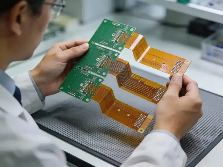
Reverse engineering a PCB for construction equipment requires a systematic understanding of its design and operational principles. The process typically begins with a physical inspection of the board to document visible components and connections. Engineers often encounter multi-layer PCBs in heavy machinery, where internal traces are not immediately accessible. This necessitates advanced techniques to map the board's architecture accurately.
One fundamental principle is the need to preserve the integrity of the original board during analysis. Non-destructive methods, such as high-resolution imaging, help capture layer details without damaging the PCB. Another key aspect is understanding the environmental stresses that construction equipment PCBs endure, including vibration, temperature fluctuations, and moisture exposure. These factors influence component selection and design, which must be considered during reverse engineering to ensure reliability.
Standards like IPC-A-600K provide guidelines for assessing PCB quality during this process. This standard helps engineers evaluate the acceptability of board conditions before proceeding with detailed analysis. Adhering to such benchmarks ensures that reverse-engineered designs meet industry expectations for performance and durability in harsh operating conditions.
Benefits of PCB Reverse Engineering in Construction Equipment
Sustaining Legacy Systems
Construction equipment often operates for decades, outlasting the availability of original parts or manufacturer support. PCB reverse engineering allows companies to recreate obsolete boards, ensuring machinery remains functional. This approach saves costs compared to full equipment replacement and minimizes downtime on critical projects.
Enhancing Customization
Reverse engineering enables modifications to existing PCBs to adapt equipment for unique tasks. For instance, updating a control system to improve efficiency or integrating new safety features becomes feasible. By understanding the original design through reverse engineering schematics, engineers can implement tailored solutions without starting from scratch.
Improving Troubleshooting
Identifying faults in complex machinery electronics can be challenging without design documentation. Reverse engineering provides detailed insights into component identification on PCBs and their interconnections. This knowledge accelerates fault diagnosis and repair, reducing operational delays.
Ensuring Compliance
Modern regulations often require updates to safety or emissions standards. Reverse engineering facilitates the redesign of PCBs to incorporate compliant components or firmware, aligning older equipment with current requirements. This process extends the usable life of machinery while meeting legal obligations.
Approaches to PCB Reverse Engineering for Construction Equipment
Schematic Recreation
Recreating a schematic from a physical PCB is a core step in reverse engineering. This involves tracing connections between components to map the circuit's logic. Engineers use manual probing with multimeters or automated continuity testers to identify signal paths. For multi-layer boards, X-ray imaging may be necessary to visualize internal traces. The resulting schematic serves as a blueprint for repairs or redesigns. Following guidelines from standards like IPC-6012E ensures that recreated schematics align with performance specifications for rigid PCBs used in heavy equipment.
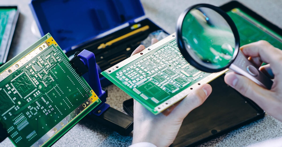
Component Identification on PCBs
Accurate component identification is critical to understanding a PCB's function. Engineers catalog resistors, capacitors, integrated circuits, and other parts, noting their specifications and roles. This often requires desoldering components for closer inspection or referencing markings against industry datasheets. Challenges arise with proprietary or obsolete parts, necessitating cross-referencing with similar components. Proper documentation during this phase supports accurate replication or substitution, maintaining the board's intended performance in rugged environments.
PCB Layout Recreation
Recreating the physical layout of a PCB involves mapping component placement and trace routing. This step is essential for manufacturing replacements or modifying designs. Software tools assist in digitizing the layout from photographs or scans, but manual verification ensures precision. Attention to layer stacking and via placement is crucial for multi-layer boards common in construction equipment. Adhering to standards like IPC-A-600K helps validate the acceptability of the recreated layout for production and use.
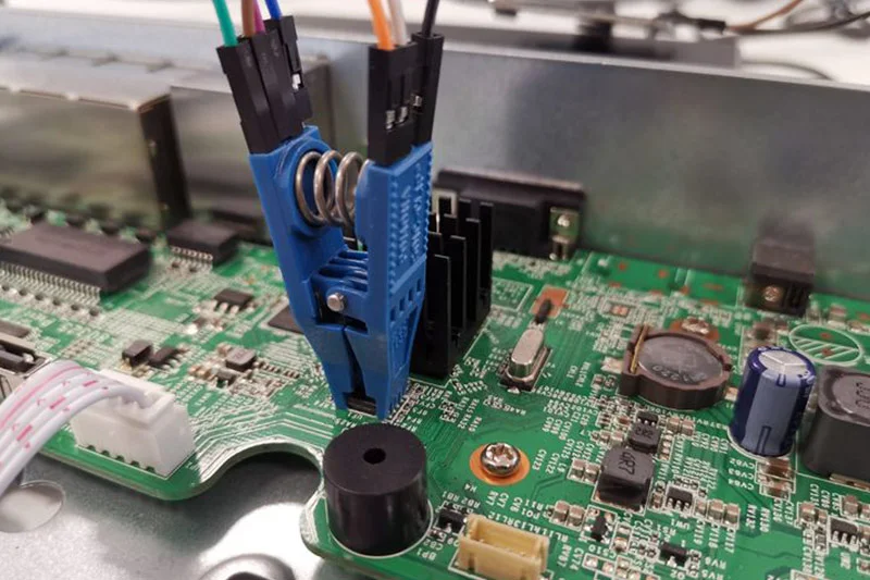
PCB Firmware Analysis
Firmware governs the behavior of electronic systems in construction equipment, making its analysis a vital part of reverse engineering. Extracting firmware from microcontrollers or memory chips requires specialized tools and expertise. Engineers analyze the code to understand control algorithms, input-output mappings, and safety protocols. This process often reveals opportunities for optimization or updates to meet new operational needs. Protecting data integrity during extraction prevents corruption, ensuring the firmware remains usable for testing or reprogramming.
Practical Solutions and Best Practices
Non-Destructive Analysis Techniques
Prioritize non-destructive methods to preserve the original PCB. Use high-resolution imaging and X-ray systems to study internal structures without disassembly. These techniques are especially useful for multi-layer boards where physical separation risks damage. Document every step with detailed notes and photographs to create a reliable reference for future work.
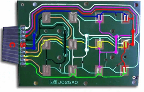
Layer-by-Layer Documentation
For complex PCBs, document each layer individually. Use color-coded diagrams to distinguish between power, ground, and signal planes. This approach simplifies schematic recreation and aids in troubleshooting. Ensure consistency by cross-verifying connections across layers before finalizing documentation.
Component Substitution Strategies
When original components are unavailable, select substitutes with equivalent electrical characteristics. Consult industry standards like JEDEC J-STD-020E for guidance on moisture sensitivity and reflow compatibility during replacement. Test substitutes under simulated operating conditions to confirm reliability in construction equipment applications.
Firmware Backup and Testing
Always create a backup of extracted firmware before analysis or modification. Use emulation tools to test firmware behavior in a controlled environment, replicating the equipment's operating conditions. This minimizes risks of unintended changes affecting performance or safety.
Challenges and Insights in Construction Equipment PCB Reverse Engineering
Construction equipment PCBs present unique challenges due to their exposure to extreme conditions. Vibration and thermal stress can degrade components, complicating component identification on PCBs and layout recreation. Engineers must account for these factors when selecting materials or redesigning boards. Additionally, proprietary firmware often includes encryption, requiring advanced skills to decode without damaging data.
An effective strategy is to collaborate with multidisciplinary teams, combining expertise in electronics, software, and mechanical systems. This ensures a holistic understanding of how the PCB integrates with the equipment. Regular calibration of testing tools also prevents errors during analysis, maintaining accuracy in schematic and firmware studies.
Conclusion
PCB reverse engineering offers a lifeline for construction equipment facing obsolescence or customization needs. By recreating schematics, identifying components, replicating layouts, and analyzing firmware, engineers can sustain legacy systems and adapt them to modern demands. The benefits include cost savings, reduced downtime, and compliance with evolving standards. Adopting systematic approaches and adhering to industry benchmarks ensures the reliability of reverse-engineered solutions. For electrical engineers in the construction sector, mastering these techniques is essential to maintaining operational efficiency and extending equipment lifespan.
FAQs
Q1: What are the main benefits of PCB reverse engineering in construction equipment?
A1: PCB reverse engineering for construction equipment helps sustain legacy systems by recreating obsolete boards, reducing downtime and replacement costs. It also supports customization for specific tasks, improves troubleshooting through detailed schematics, and ensures compliance with modern safety standards. This process preserves investments in heavy machinery and maintains operational continuity.
Q2: How does component identification on PCBs work during reverse engineering?
A2: Component identification on PCBs involves cataloging parts like resistors and integrated circuits by their markings and specifications. Engineers may desolder components for inspection and cross-reference them with datasheets. This step is crucial for replication or substitution, especially with obsolete parts, ensuring the board's functionality in rugged construction environments.
Q3: What challenges arise during PCB firmware analysis for heavy machinery?
A3: PCB firmware analysis for construction equipment often faces challenges like encrypted code or proprietary formats, requiring specialized tools to extract and decode. Preserving data integrity during extraction is critical. Understanding control algorithms and safety protocols also demands expertise, as errors can impact equipment performance or safety.
Q4: Why is PCB layout recreation important for construction equipment repairs?
A4: PCB layout recreation is vital for manufacturing replacement boards or modifying designs for construction equipment. It maps component placement and trace routing, ensuring compatibility with the original system. Accurate recreation, validated by industry standards, maintains reliability under harsh conditions, supporting seamless repairs and upgrades.
References
IPC-A-600K — Acceptability of Printed Boards. IPC, 2020.
IPC-6012E — Qualification and Performance Specification for Rigid Printed Boards. IPC, 2017.
JEDEC J-STD-020E — Moisture/Reflow Sensitivity Classification. JEDEC, 2014.