Introduction
In the current era of power electronics, heat is the primary enemy of reliability and performance. As components like high power LEDs, power transistors, and converters become more densely packed, the inability of standard FR4 substrates to manage thermal loads has led to the rise of Metal Core Printed Circuit Boards or MCPCBs. Among these, copper core PCB materials represent the pinnacle of thermal management technology. By utilizing a copper base instead of aluminum or fiberglass, engineers can achieve thermal conductivity levels that were previously unattainable, ensuring that critical components operate within safe temperature margins even under extreme stress.
For technical decision makers and hardware engineers, understanding the nuances of copper core materials is essential for high performance design. This guide establishes a systematic framework for evaluating copper core substrates, helping you understand their structural benefits and how they integrate into a broader thermal management strategy.
Foundational Framework of Copper Core PCB Material and MCPCBs
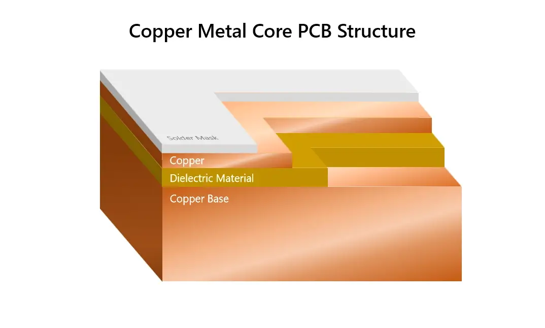
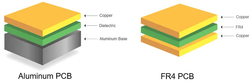
To effectively implement copper core materials, it is necessary to understand their unique architecture and how they differ from other metal core solutions. A typical copper core PCB consists of a circuit layer, a high performance dielectric layer, and a solid copper base. The primary differentiator is the copper base itself, which offers a thermal conductivity of approximately 380 to 400 Watts per meter Kelvin, nearly double that of aluminum.
Engineers must also distinguish between standard metal core designs and thermoelectric separation architectures. In a standard copper core board, the dielectric layer sits between the copper base and the circuit layer. In more advanced thermoelectric separation designs, the thermal pad of a component is directly bonded to the copper core, removing the dielectric barrier and allowing for the fastest possible heat transfer. This classification helps designers select the appropriate material stackup based on the heat flux of their specific application.
Thermal Performance of Copper Core PCB for High Power Applications
The decision to utilize a copper core is almost always driven by a requirement for superior thermal dissipation that exceeds the capabilities of other materials. While aluminum is sufficient for many LED applications, copper is reserved for the most demanding environments where every degree of cooling is vital for system stability.
Efficient thermal routing depends on a detailed heat dissipation comparison that weighs the conductivity of copper against other metal substrates. This evaluation is critical when designing for automotive power modules or high frequency communication equipment where localized heat spots can cause catastrophic failure. By understanding the thermal resistance of the entire stackup, engineers can predict the junction temperature of semiconductors more accurately. This enables the creation of more compact designs that do not rely on large, external cooling systems, effectively using the PCB itself as the primary heat sink.
Choosing Metal Core Materials: Comparing Copper vs. Aluminum for Thermal Performance
Choosing between different metal core materials involves more than just comparing raw thermal numbers. Engineers must balance performance requirements with mechanical constraints, weight considerations, and project budgets to arrive at the most viable solution for mass production.
Navigating the complexities of selecting metal core substrates requires a holistic view of the manufacturing process and the end use environment. While copper offers the best thermal performance, it is also heavier and more expensive than aluminum. Consequently, it is often selected for high density power electronics or aerospace applications where performance and reliability take precedence over cost. Designers must also consider the coefficient of thermal expansion, as copper behaves differently than aluminum when subjected to the high temperatures of reflow soldering. A structured selection process ensures that the chosen material supports both the thermal goals and the mechanical longevity of the final product.
Dynamic Interaction Between Material Layers
In a copper core system, the individual layers do not function in isolation. The synergy between the copper base, the dielectric, and the copper foil on the circuit layer determines the overall reliability of the board. For instance, using a high conductivity copper base with a low quality dielectric layer would create a thermal bottleneck, nullifying the benefits of the expensive copper substrate.
Understanding these relationships allows engineers to optimize the entire thermal path. In high frequency applications, the copper base also acts as a ground plane, providing electromagnetic shielding alongside thermal management. This dual role simplifies the design of complex power amplifiers and transmitters. By viewing the material stackup as a single, integrated thermal and electrical unit, teams can avoid common pitfalls such as delamination or solder joint fatigue caused by mismatched thermal expansion rates.
Manufacturing Realities and Challenges for Copper Core PCB
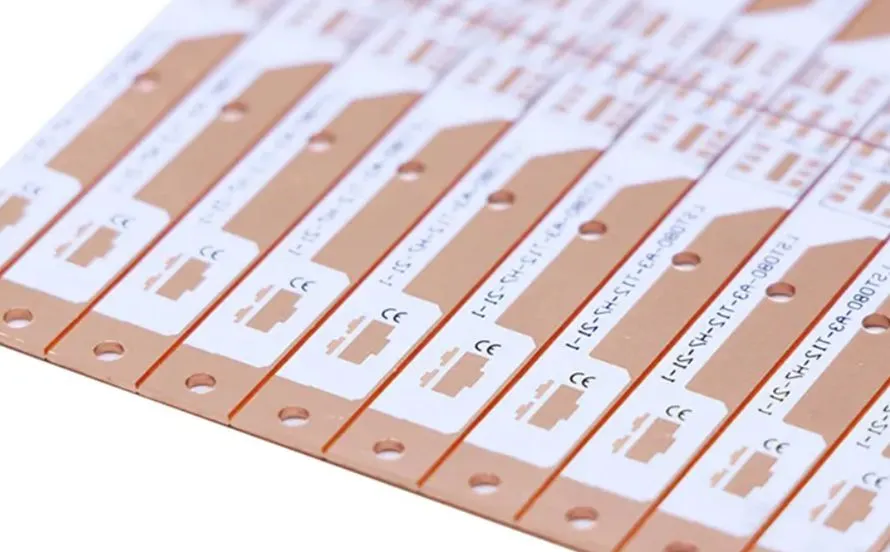
From a manufacturing standpoint, copper core boards require specialized fabrication techniques that differ from standard rigid or aluminum boards. The density and hardness of copper affect the drilling and routing processes, requiring adjusted tool speeds and feed rates. Furthermore, the chemical processing of copper bases requires careful handling to prevent oxidation during the manufacturing cycle.
Technical managers should prioritize early collaboration with fabrication partners who have proven experience with heavy copper and metal core technologies. This collaboration ensures that the design is optimized for manufacturing, which can significantly reduce lead times and improve yields. From a cost perspective, the investment in copper core materials is often justified by the increased lifespan of the electronic components and the reduction in system level cooling requirements. In industries such as renewable energy and high performance computing, the reliability afforded by copper core technology is a key competitive advantage.
Summary of Copper Core Engineering Principles
Mastering copper core PCB materials involves a transition from traditional electrical layout to a specialized focus on thermal engineering. By leveraging the extreme conductivity of copper, engineers can solve the most difficult heat management challenges in modern electronics. The integration of solid material frameworks, detailed performance comparisons, and strategic selection criteria provides the foundation necessary for building robust hardware.
As power densities continue to increase across all sectors, the role of copper core substrates will become even more central to electronic architecture. Focusing on the principles of thermal resistance, material synergy, and manufacturing compatibility ensures that every design choice contributes to a stable and efficient system. Adhering to these industry recognized considerations allows engineering teams to push the limits of power electronics while maintaining the highest standards of quality and reliability.