Introduction
Flexible circuits, also known as flex PCBs, have revolutionized bendable electronic design by allowing electronics to conform to irregular shapes and withstand repeated bending. Embedding components directly into these flexible substrates takes this innovation further, integrating resistors, capacitors, and even active devices within the layers of the circuit. This approach minimizes overall size, reduces parasitic inductance, and enhances reliability in dynamic environments. For electric engineers tackling compact systems, understanding embedded components in flexible circuits is essential for optimizing performance in applications ranging from wearables to aerospace. This article delves into the design considerations that ensure functionality and longevity, while exploring key flex PCB applications. By addressing mechanical, thermal, and electrical challenges, engineers can leverage these technologies effectively.
What Are Embedded Components in Flexible Circuits and Why Do They Matter?
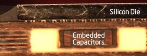
Embedded components in flexible circuits refer to passive or active devices integrated directly into the dielectric layers or copper traces of a flex PCB, rather than mounted on the surface. This technique contrasts with traditional surface-mount technology by burying elements like thin-film resistors or capacitors within the substrate, creating a seamless, low-profile structure. The process typically involves laser drilling cavities, placing components, and laminating additional layers to encapsulate them securely.
The relevance of embedding components in flex PCBs stems from the demands of modern electronics, where space constraints and mechanical flexibility are paramount. In bendable electronic design, surface-mounted parts are prone to cracking under flexure, leading to failures in high-motion scenarios. Embedded versions distribute stress more evenly, improving cycle life and signal integrity. Industries benefit from higher component density, which supports miniaturization without sacrificing performance. Moreover, this method aligns with trends toward thinner profiles, making it ideal for flex PCB applications in constrained environments.
Technical Principles of Embedding Components in Flex PCBs
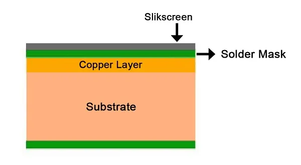
The foundation of flexible PCB design with embedded components lies in material selection and layer stackup. Polyimide films serve as the primary substrate due to their excellent thermal stability and flexibility, allowing repeated bending without delamination. Components are embedded by forming cavities through precise laser ablation or photoresist patterning, followed by precise placement and lamination under controlled pressure and temperature. Adhesives or resin systems fill any gaps, ensuring electrical isolation and mechanical integrity.
Electrical performance hinges on minimizing parasitics during embedding. Proximity to signal traces reduces inductance, which is critical for high-frequency signals in bendable electronic design. However, the flexible nature introduces challenges like trace cracking at bend zones. Engineers must model strain distribution using finite element analysis to predict failure points. Thermal expansion mismatch between components and substrate can induce microcracks, necessitating materials with compatible coefficients of thermal expansion.
Mechanical principles govern the durability of these designs. Flex circuits endure cyclic bending, so embedded components must withstand shear and tensile forces. Guidelines from IPC-2223 emphasize bend radii that prevent excessive strain on inner layers, where compression is highest. Multi-layer constructions require symmetrical stackups to avoid warping during lamination. Air gaps or fillers between flex and rigid sections in hybrid designs further mitigate stress concentrations.
Key Design Considerations for Embedded Components in Flexible Circuits
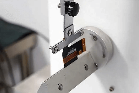
When pursuing flexible PCB design with embedded components, engineers prioritize mechanical reliability. Bend radius selection is crucial; tighter radii increase strain on embedded elements, potentially causing delamination or fatigue. Standards like IPC-6013 specify qualification tests, including flex endurance cycling up to thousands of bends at defined radii. Components should be placed away from high-flex zones, ideally in rigidized areas reinforced with stiffeners like polyimide or FR-4.
Thermal management poses another challenge in embedding components in flex PCBs. Heat from embedded actives dissipates poorly through thin dielectrics, risking hotspots during operation. Designers incorporate thermal vias or high-conductivity fillers around components to channel heat to outer layers. Solder reflow compatibility requires low-moisture sensitivity, aligning with JEDEC J-STD-020 classifications to prevent popcorning. Simulation tools help predict junction temperatures under flex-induced deformation.
Electrical integrity demands careful trace routing and impedance control. Embedded passives alter local capacitance, so engineers adjust trace widths accordingly. Vias connecting to embedded devices must avoid flex zones to prevent cracking. Testing protocols verify continuity after bending cycles. Signal shielding layers reduce crosstalk in dense layouts.
Material compatibility ensures long-term stability. Dielectrics must bond firmly to component metallizations without voids. Laser-drilled cavities require clean sidewalls for reliable plating if interconnects are needed. Coverlay films protect outer layers while maintaining flexibility.
Fabrication tolerances influence yield. Precise cavity depth controls component seating, preventing shorts. Lamination pressure uniformity avoids bubbles that compromise insulation resistance.
Best Practices for Flexible PCB Design with Embedded Components
Adopt a structured design flow starting with stackup planning. Define flex and rigid zones early, positioning embedded components in low-strain regions. Use symmetrical builds to minimize curl, incorporating filler layers for planarity. Simulate mechanical stress with tools accounting for polyimide's anisotropic properties.
Select components suited for embedding, such as discrete passives with flexible terminations. Thin-film resistors offer stability under flexure compared to thick-film alternatives. Verify supplier data on bend cycle ratings.
Incorporate design for testability. Exposed test points on rigid tails facilitate in-circuit verification post-assembly. Optical inspection confirms cavity fill and alignment.
Assembly processes adapt to flex substrates. Low-temperature lamination preserves component integrity. Avoid aggressive chemicals that degrade polyimides.
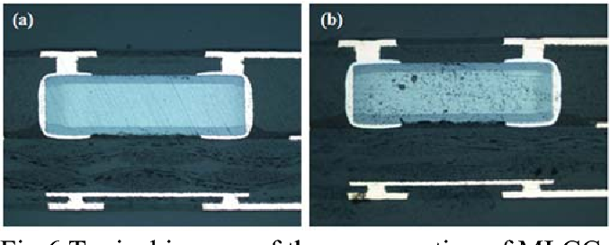
Qualification follows IPC-6013 protocols, including thermal shock, humidity exposure, and flex cycling. Cross-section analysis reveals voids or cracks early.
Challenges and Troubleshooting in Flex PCB Applications
Common pitfalls include inadequate bend radius planning, leading to trace fractures near embedded sites. Engineers troubleshoot by analyzing failure modes through dye-and-peel tests or scanning electron microscopy. Adjusting radius or adding strain relief slits resolves many issues.
Thermal runaway in densely packed designs manifests as delamination. Mitigate with wider heat spreaders or reduced power densities. Monitor via infrared thermography during prototypes.
Electrical shorts from migration arise in humid environments. Bake-out processes per JEDEC guidelines precondition boards. Enhanced coverlay thickness prevents ingress.
Yield losses from cavity misalignment demand tighter tolerances. Iterative laser parameter tuning improves precision.
Hybrid rigid-flex designs risk Z-axis expansion mismatch. Gradual transitions with tapered stiffeners distribute loads evenly.
Real-World Flex PCB Applications with Embedded Components
In wearable electronics, embedded components in flexible circuits enable skin-conformable sensors with integrated amplifiers. This bendable electronic design withstands body movements while maintaining bio-signal fidelity. Medical devices like implantable leads benefit from miniaturized profiles, reducing tissue trauma.
Aerospace harnesses use flex PCBs for wing actuators, where embedded capacitors filter noise in harsh vibrations. Automotive sensors in curved dashboards leverage embedding for vibration resistance.
Consumer gadgets, such as foldable displays, integrate drivers directly into flex substrates for seamless bending.
These flex PCB applications demonstrate how embedding enhances reliability in dynamic settings.
Conclusion
Embedded components in flexible circuits represent a pinnacle of flexible PCB design innovation, balancing compactness with robustness. Key considerations around mechanical strain, thermal dissipation, and electrical performance guide successful implementations. Adhering to standards like IPC-2223 and IPC-6013 ensures qualification for demanding flex PCB applications. Engineers gain actionable insights to troubleshoot challenges and optimize bendable electronic design. As demands for miniaturization grow, this technology will expand into more sectors, driving reliable, high-performance systems.
FAQs
Q1: What are the main advantages of embedding components in flex PCBs?
A1: Embedding components in flex PCBs reduces overall height, lowers parasitics for better signal integrity, and improves mechanical reliability under bending. This supports compact flex PCB applications like wearables. Design challenges include precise cavity formation and material matching, but benefits outweigh them for high-density needs. Standards guide qualification to ensure longevity.
Q2: How does flexible PCB design change with embedded components?
A2: Flexible PCB design shifts to incorporate cavities and adjusted stackups, prioritizing low-strain placement for embedded components flexible circuits. Bend radii must exceed minimums per IPC guidelines to avoid fatigue. Simulation verifies strain distribution. This enhances bendable electronic design suitability for dynamic uses.
Q3: What are common flex PCB applications for embedded components?
A3: Flex PCB applications include medical implants, aerospace controls, and consumer foldables, where embedding components flexible circuits enables thin, reliable profiles. Vibration and flexure resistance improves over surface-mount. Engineers select based on cycle life requirements.
Q4: What standards apply to embedding components in flex PCBs?
A4: IPC-2223 covers design for flexible circuits, while IPC-6013 specifies performance qualification, including bend testing. JEDEC J-STD-020 addresses moisture handling during assembly. These ensure embedded components in flex PCBs meet reliability thresholds.
References
IPC-2223 — Sectional Design Standard for Flexible Printed Boards and Rigid-Flexible Printed Boards. IPC.
IPC-6013 — Qualification and Performance Specification for Flexible/Rigid-Flexible Printed Boards. IPC.
IPC-7092 — Design and Assembly Process Implementation for Embedded Components. IPC.
JEDEC J-STD-020 — Moisture/Reflow Sensitivity Classification of Nonhermetic Solid State Surface Mount Devices. JEDEC.