Introduction
Rigid-flex PCBs integrate rigid and flexible sections into a single board, enabling compact designs for applications in medical devices, aerospace, and consumer electronics. Electric engineers often start with prototypes to validate functionality, but transitioning to production volumes introduces unique challenges in the rigid-flex PCB manufacturing process. This scale-up requires careful planning to maintain reliability, control costs, and ensure high yields. Factors like material handling, lamination precision, and testing protocols become critical as production volumes increase. Understanding these elements helps engineers optimize the rigid-flex PCB manufacturing scale-up for efficient high-volume output.
Understanding Rigid-Flex PCBs and the Need for Scale-Up
Rigid-flex PCBs combine the structural stability of rigid boards with the bendability of flexible circuits, allowing three-dimensional assembly in space-constrained environments. They typically feature multiple layers where polyimide films form flexible regions and FR-4 cores provide rigidity in others. As designs move from prototype to production, the focus shifts from feasibility to repeatability and cost-effectiveness in rigid-flex PCB production volume. Engineers must address how small-batch processes differ from high-volume runs, where panel utilization and automation play larger roles. This transition matters because failures in scaling can lead to yield losses, delayed timelines, and escalated rigid-flex PCB manufacturing costs.
Key Stages in the Rigid-Flex PCB Manufacturing Process
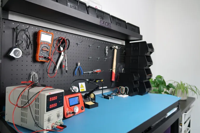
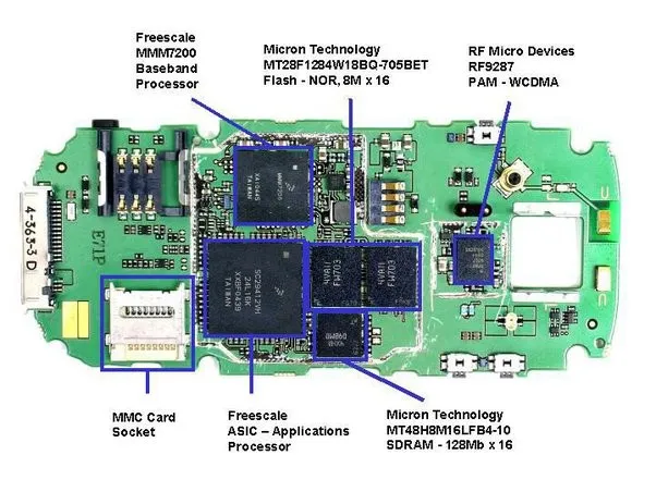
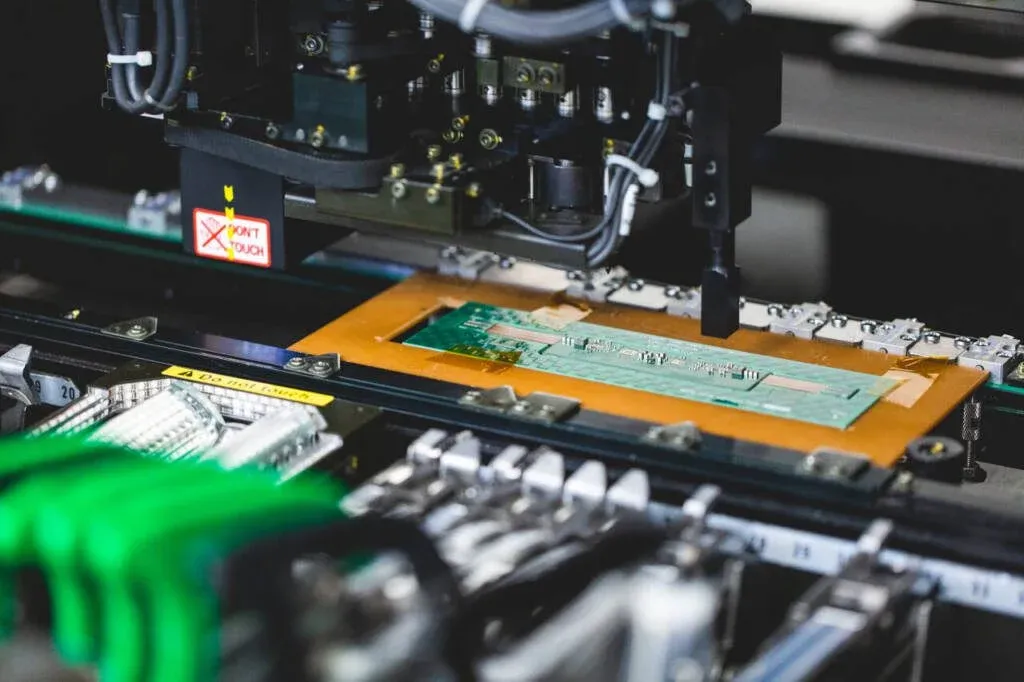
The rigid-flex PCB manufacturing process begins with material selection, where engineers choose compatible substrates like polyimide for flex areas and epoxy-based cores for rigid sections. Inner layers are etched and imaged before sequential lamination builds the stackup, bonding flex and rigid sections with adhesives or laser vias. Outer layers undergo similar patterning, followed by coverlay application to protect flex regions. Drilling, plating, and routing complete the panelization, with flex outlines cut precisely to avoid tears. In prototype stages, these steps use smaller panels and manual inspections, but production demands automated optical inspection and larger panel sizes for efficiency.
Compliance with IPC-6013E ensures qualification and performance for flexible and rigid-flex boards during this process. Engineers should verify layer-to-layer registration, especially at flex-rigid transitions, to prevent misalignment under thermal stress.
Challenges in Rigid-Flex PCB Manufacturing Scale-Up
Scaling rigid-flex PCB production volume amplifies issues like warpage, caused by differing coefficients of thermal expansion between rigid FR-4 and flexible polyimide materials. During lamination, uneven pressure or curing can distort the board, complicating subsequent drilling and assembly. Yield rates drop if prototypes overlook production tooling, such as fiducials for panel alignment or carrier fixtures for handling thin flex sections. Electrical testing becomes more complex with bend-induced microcracks, requiring specialized probes. Additionally, rigid-flex PCB manufacturing costs rise due to material waste from low panel utilization in early runs and rework from defects.
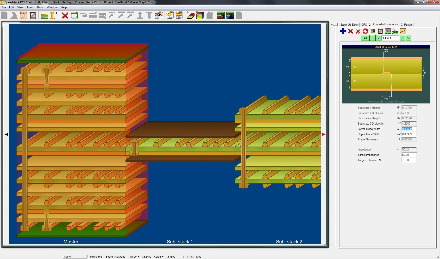
Another hurdle involves maintaining impedance control across flex bends, where dynamic flexing affects signal integrity in high-speed designs. Engineers transitioning to scale-up often underestimate the need for process validation runs to baseline yields before full production.
Factors Influencing Rigid-Flex PCB Manufacturing Costs
Rigid-flex PCB manufacturing costs depend on layer count, flex region complexity, and minimum feature sizes, with high-volume runs benefiting from economies of scale. Prototype costs dominate due to setup fees, small panel sizes, and extensive testing, while production shifts emphasis to yield optimization and material efficiency. Adhesive bonding and coverlay materials add expense compared to rigid boards, and custom tooling for routing flex outlines increases upfront investment. Engineers can mitigate costs by standardizing stackups and minimizing vias in flex areas. Selecting rigid-flex PCB manufacturing partners with proven high-volume capabilities further controls expenses through better pricing and faster turnaround.
Volume thresholds typically mark the shift, where orders above certain panel quantities enable automated processes that reduce per-unit costs significantly.
Best Practices for Successful Rigid-Flex PCB Production Volume Ramp-Up
Start with design for manufacturability reviews early, incorporating IPC-2223 guidelines for flex and rigid-flex sectional design to avoid common pitfalls like excessive bend radii. Conduct pilot runs at intermediate volumes to identify warpage or registration issues before committing to full production. Implement statistical process control for key metrics like layer alignment and plating thickness uniformity. Use carrier panels during assembly to stabilize flex sections, preventing component shifts in reflow. Rigorous incoming material inspection ensures consistency, as variations in polyimide thickness can cascade into defects.

Partner selection is crucial; choose rigid-flex PCB manufacturing partners certified to ISO 9001:2015 for quality management, with experience in your application's volume and tolerances. Document all process parameters from prototypes to enable seamless transfer.
Troubleshooting Common Scale-Up Issues
Warpage often emerges post-lamination; engineers can counter it by balancing copper distribution and using symmetric stackups. If yields falter in production, audit drilling registration against prototype data, adjusting for panel expansion. Flex tears during routing signal inadequate support; switch to scored panels or waterjet cutting for precision. For cost overruns, analyze scrap data to refine panel nesting. These factory-driven insights align with standard protocols, ensuring robust rigid-flex PCB manufacturing scale-up.
Conclusion
Scaling rigid-flex PCB manufacturing from prototype to production demands attention to process differences, cost drivers, and quality controls. By adhering to standards like IPC-6013E and IPC-2223, engineers achieve reliable high-volume output while managing rigid-flex PCB production volume effectively. Proactive DFM, pilot validation, and strategic partner choices minimize risks and optimize rigid-flex PCB manufacturing costs. This approach not only accelerates time-to-market but also enhances product reliability in demanding applications. Electric engineers equipped with these insights can confidently navigate the transition for successful deployment.
FAQs
Q1: What are the main steps in the rigid-flex PCB manufacturing process during scale-up?
A1: The rigid-flex PCB manufacturing process involves material layup, sequential lamination, imaging, drilling, plating, and final routing with coverlay application. Scale-up emphasizes larger panels, automation, and IPC-6013E compliance for performance qualification. Pilot runs validate yields before full rigid-flex PCB production volume. This structured approach ensures alignment and minimizes defects across flex-rigid zones.
Q2: How do rigid-flex PCB manufacturing costs change with production volume?
A2: Rigid-flex PCB manufacturing costs decrease per unit as volumes rise, thanks to better panel utilization and reduced setup overhead. Prototypes incur high fixed costs from custom tooling, while high-volume runs leverage automation for efficiency. Factors like layer count and flex complexity influence pricing, but optimized designs lower overall expenses. Engineers should forecast based on yield projections.
Q3: What should electric engineers look for in rigid-flex PCB manufacturing partners?
A3: Rigid-flex PCB manufacturing partners should demonstrate expertise in high-volume scale-up, ISO 9001:2015 certification, and adherence to IPC standards. Evaluate their experience with similar stackups, yield data, and fixturing capabilities for flex handling. Strong communication and DFM feedback prevent costly iterations. Proven track records in your industry ensure reliable rigid-flex PCB production volume.
Q4: Why is warpage a key challenge in rigid-flex PCB manufacturing scale-up?
A4: Warpage arises from thermal mismatches between rigid and flex materials during lamination and cooling. In prototypes, small sizes mask issues, but production panels amplify distortions affecting registration. Mitigation involves symmetric designs and controlled curing per IPC-2223. Testing with gauges confirms flatness before assembly, supporting smooth rigid-flex PCB manufacturing scale-up.
References
IPC-6013E - Qualification and Performance Specification for Flexible/Rigid-Flexible Printed Boards. IPC, 2021
IPC-2223E - Sectional Design Standard for Flexible/Rigid-Flexible Printed Boards. IPC, 2023
ISO 9001:2015 - Quality Management Systems. ISO, 2015