Why Is Accurate PCB Board Power Calculation Essential?
Precisely calculating the power requirements for an electronic PCB forms the bedrock of any successful electronic design. This calculation dictates the overall energy consumption of your board, guides the selection of an appropriate power supply, and ensures that all components operate safely within their specified limits. Overlooking these crucial power considerations can lead to severe consequences such as overheating, permanent component damage, or complete system failure. By accurately determining power in watts, considering various voltage levels, and understanding the dynamics of heat generation, you can design a fast turn custom PCB that consistently performs reliably under diverse operational conditions.
The Foundation of Reliability
Accurate power calculation isn't just about functionality; it's about building a foundation of reliability. It allows designers to anticipate and mitigate potential issues, leading to more robust and long-lasting electronic products.
Fundamental Concepts in PCB Power Calculation
Before delving into the detailed calculation process, it’s essential to clarify some core concepts related to power, its units (watts), voltage, the role of various components, and the critical aspect of heat generation within an electronic PCB.
What Does "Power" Mean in an Electronic PCB Context?
Power, quantitatively measured in watts (W), signifies the rate at which electrical energy is either consumed or dissipated within a circuit. On a electronic HDI PCB, this power is distributed among its myriad components, including resistors, capacitors, integrated circuits (ICs), and other active or passive elements. The fundamental formula for calculating power is:
Power (P) = Voltage (V) × Current (I)
Here, voltage is expressed in volts (V), and current is measured in amperes (A). This foundational equation serves as the crucial starting point for determining the cumulative power consumption of your entire PCB assembly.
The Influence of Voltage in Power Calculations
Voltage represents the electrical potential difference that drives the flow of current through the components on your PCB. The majority of electronic PCBs operate at specific, regulated voltage levels, commonly 3.3V, 5V, or 12V, depending on the requirements of the integrated components. A precise understanding of each component's operating voltage is indispensable, as it directly impacts its individual power consumption. For example, a component drawing 0.2A of current while operating at 5V will consume 1 watt of power (5V × 0.2A = 1W).
Component-Specific Power Consumption
Individual components on an electronic PCB exhibit varying power consumption characteristics:
● Resistors: These components dissipate power primarily as heat, calculated using the formula P = I² × R, where R denotes resistance in ohms (Ω).
● Integrated Circuits (ICs) and Microcontrollers: Their power consumption is typically specified in their respective datasheets, usually in milliwatts (mW) or watts (W).
● LEDs: Light-emitting diodes consume power based on their forward voltage and current, often around 0.06W per standard LED (e.g., 3V × 0.02A).
Each component contributes to the overall power budget of the PCB, making it imperative to account for every element in the design.
The Challenge of Heat Generation in PCBs
Whenever electrical power is consumed or dissipated, a significant portion of it is often converted into heat. Excessive heat generation poses a substantial risk, potentially damaging components, degrading their performance, or even leading to catastrophic system failure. For instance, a resistor dissipating 2W of power as heat can significantly elevate the local temperature if adequate thermal management is not implemented. Therefore, incorporating effective heat dissipation techniques, such as thermal vias or dedicated heat sinks, is vital for high-power designs.
Step-by-Step Guide to Calculating PCB Board Power
Having established the foundational concepts, let’s now proceed with a practical, systematic approach to calculating the power consumption of your electronic PCB. Following these steps meticulously will help ensure both accuracy and reliability in your design.
Step 1: Catalog All Components and Their Electrical Specifications
Begin by compiling an exhaustive list of every single component intended for your PCB. For each component, consult its respective datasheet or manufacturer's specifications to record its typical operating voltage and current draw. For example:
● Microcontroller: 3.3V, 0.05A (resulting in 0.165W)
● LEDs (5 units): 2V, 0.02A each (totaling 0.04W per LED, or 0.2W for all five)
● Resistors (2 units): Each carrying 0.5A through 10Ω (dissipating 2.5W per resistor, for a total of 5W)
This detailed inventory provides a clear understanding of the individual power requirements before their summation.
Step 2: Calculate Individual Component Power Consumption
Utilize the fundamental power formula, P = V × I, to calculate the power consumption for all components where voltage and current are known. For resistors, if current and resistance values are available, use the formula P = I² × R. Once calculated, sum these individual values to obtain a subtotal for each component type. Continuing our example:
● Microcontroller: 0.165W
● LEDs: 0.2W
● Resistors: 5W
● Total Initial Power: 0.165W + 0.2W + 5W = 5.365W
Step 3: Integrate Efficiency Losses
It is crucial to recognize that not all power supplied to a PCB is ultimately utilized by the components; a portion is inevitably lost as heat or through inefficiencies in power conversion processes (e.g., within voltage regulators). A typical efficiency factor for DC-DC converters ranges from approximately 80% to 90%. If your PCB incorporates a voltage regulator with, for example, 85% efficiency, the actual power demanded from your primary power supply will be higher than the sum of component consumption:
Adjusted Power = Total Initial Power / Efficiency = 5.365W / 0.85 = 6.31W
This adjusted value accurately represents the minimum power capacity your power supply must reliably deliver.
Step 4: Account for Multiple Voltage Domains
Many complex PCBs operate with multiple distinct voltage levels (e.g., 3.3V for digital logic, 12V for motor drivers). In such cases, calculate the power consumption separately for each voltage domain and then sum these individual domain totals for the overall board power. For instance, if components operating at 3.3V consume 2W, and components operating at 12V consume 4W, the total power is 6W. However, this scenario necessitates either separate power supplies or distinct voltage regulators for each operational domain.
Step 5: Evaluate Heat Generation and Implement Dissipation Strategies
Once the total power in watts is accurately determined, the next critical step is to estimate how much of this power will be converted into heat. Components such as power resistors and certain power ICs often dissipate a significant majority of their consumed power as heat. For example, if your PCB consumes a total of 6.31W and 4W of that originates from resistive losses, effective thermal management becomes paramount. This might involve strategic layout, the incorporation of thermal vias, or the use of active cooling solutions. A useful rule of thumb is that 1W of power dissipation in a confined area can elevate the local temperature by 10-20°C if not adequately cooled.
What Factors Influence PCB Power Consumption?
Beyond the individual components and their operating voltages, several other factors significantly influence the overall power consumption of an electronic PCB. Understanding these elements can aid in optimizing your design for better performance and efficiency.
Operating Frequency
High-frequency operations, as seen in microcontrollers or RF circuits, invariably increase power consumption primarily due to increased switching losses within the semiconductors. For example, a microcontroller operating at 100MHz might consume up to 50% more power compared to the same device running at 50MHz, even if all other operational parameters remain constant.
Ambient Temperature
Elevated ambient temperatures can lead to an increase in power dissipation, as semiconductor components may draw more current (due to increased leakage currents) to maintain their performance characteristics. A PCB operating in an environment at 40°C might consume 10-15% more power than an identical board functioning at 25°C.
Power Supply Design Efficiency
The fundamental design and type of power supply or voltage regulator utilized critically impact the overall system efficiency. Linear regulators, for instance, typically exhibit lower efficiencies (ranging from 50-60%) compared to their switching regulator counterparts (which can achieve 80-95% efficiency). Lower efficiency directly translates to higher power losses, which manifest as increased heat generation and greater power draw from the primary source.
Practical Tips for Managing Power and Heat in PCB Design
Effective power management is inextricably linked with robust thermal control. Here are some practical tips to ensure your electronic PCB operates reliably and efficiently.
Utilize Power-Efficient Components
Whenever feasible, select low-power versions of components. For example, choose a microcontroller that offers a low-power or sleep mode, capable of reducing its current consumption to mere microamps during idle states. This proactive choice can significantly reduce overall power requirements.
Optimize PCB Layout for Thermal Performance
Strategically position high-power components away from heat-sensitive areas and ensure ample spacing to facilitate natural airflow. Employ wider traces for power delivery lines to minimize electrical resistance and, consequently, reduce heat buildup. For instance, a trace intended to carry 2A of current should be at least 0.5mm wide for a 1oz copper layer to minimize both voltage drop and localized heating.
Integrate Robust Heat Dissipation Techniques
Incorporate thermal vias strategically placed directly under high-power components. These small, plated holes efficiently transfer heat from the component to other PCB layers or to an attached heat sink. For a component dissipating 3W, the inclusion of 4-6 thermal vias (each approximately 0.3mm in diameter) can reduce its localized temperature by 5-10°C.
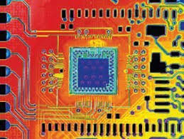
Implement Thorough Monitoring and Testing
After the PCB has been assembled, use a multimeter to measure the actual current draw from various sections of the board and compare these readings against your initial calculations. Furthermore, employ thermal imaging cameras to precisely identify any hotspots, allowing you to address them proactively before they lead to critical failures.
Common Mistakes to Avoid When Calculating PCB Power
Even seasoned designers can fall prey to certain errors during the power calculation process. Here are some common pitfalls to actively avoid:
● Neglecting Idle or Standby Power: Many components consume a measurable amount of power even when they are not actively performing their primary function. Always consult component datasheets for specified standby or quiescent current consumption.
● Underestimating Heat Generation: Failing to adequately account for the heat generated by components can lead to thermal runaway conditions, where components progressively overheat and ultimately fail.
● Overlooking Voltage Drops: Extended traces or suboptimal connections can result in significant voltage drops across the board, which reduces the actual voltage supplied to components and negatively impacts their performance and reliability.
Conclusion: Mastering PCB Power Calculation for Superior Designs
Accurately calculating PCB board power is an indispensable skill for anyone engaged in electronic design. By thoroughly understanding the intricate interplay of power in watts, the specific requirements of various components, the impact of voltage levels, and the dynamics of heat generation, you can create highly efficient and reliably performing electronic PCBs that precisely meet your project’s demands. Begin by compiling a detailed inventory of all components, meticulously calculate the power for each, adjust for any efficiency losses, and design with proactive heat management as a core principle. By following these steps, you will ensure your PCB operates safely and consistently delivers optimal performance.
Whether your endeavor is a modest hobby project or a complex industrial system, precise power calculation remains the cornerstone of success. Utilize the comprehensive guidelines and practical tips provided in this guide to refine your design methodology and build superior electronic systems. For professional assistance in PCB manufacturing and precision assembly, trust a reputable partner to meticulously transform your innovative ideas into high-quality, tangible products.