Introduction
High-frequency PCB fabrication involves creating printed circuit boards capable of handling signals above 1 GHz, often extending into microwave and millimeter-wave ranges. Selecting the appropriate PCB material directly impacts signal integrity, power handling, and overall reliability in demanding applications like 5G infrastructure, automotive radar, and aerospace systems. Engineers must prioritize properties such as dielectric constant, thermal conductivity, and coefficient of thermal expansion to mitigate losses and ensure stability. Incorrect material choices can result in excessive insertion loss, phase shifts, or thermal runaway, compromising system performance. This guide provides a systematic approach for electric engineers to evaluate and select materials aligned with fabrication processes and performance needs. By focusing on key material characteristics, teams can achieve robust designs that meet stringent operational requirements.
Understanding High-Frequency PCB Fabrication and Material Demands
High-frequency PCB fabrication refers to the production of boards optimized for rapid signal propagation with minimal distortion. These PCBs require materials with low dielectric constant to reduce signal delay and low dissipation factor to limit energy loss as heat. In practice, frequencies from 1 GHz to over 40 GHz necessitate careful material selection to prevent issues like impedance mismatches and radiation losses. PCB material choices influence not only electrical performance but also manufacturability, including drilling, plating, and lamination processes. Engineers often face trade-offs between cost, availability, and performance, making a thorough evaluation essential. Industry standards guide these decisions, ensuring consistency across fabrication workflows.
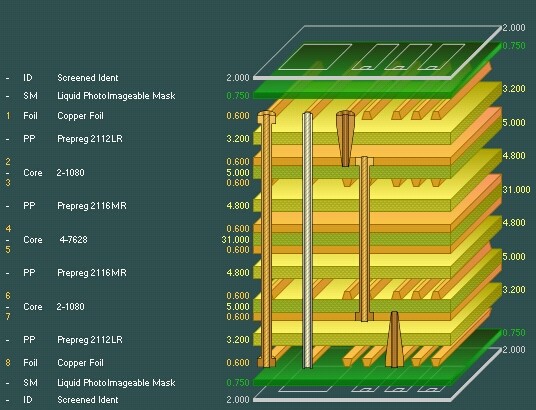
The relevance of material selection intensifies in multilayer designs where signal paths traverse multiple dielectric layers. Variations in material properties across layers can introduce skew or crosstalk, degrading high-speed signals. Fabrication challenges, such as resin flow during pressing or copper peel under thermal stress, further underscore the need for compatible materials. Electric engineers benefit from understanding how PCB material interacts with fabrication parameters like press cycles and cure temperatures. Ultimately, the right material enables high-yield production while supporting long-term reliability in harsh environments.
Key Material Properties for High-Frequency Applications
Dielectric Constant and Dissipation Factor
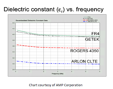
The dielectric constant, often denoted as Dk or εr, measures a material's ability to store electrical energy in an electric field. For high-frequency PCB fabrication, a low and stable Dk, typically below 3.5, is critical to minimize signal propagation delay and maintain controlled impedance. Variations in Dk with frequency or temperature can cause timing errors in synchronized systems. Engineers measure Dk using standardized test methods to predict behavior across the operational bandwidth.
Complementing Dk is the dissipation factor, Df or tan δ, which quantifies dielectric losses. Low Df values, under 0.005 at 10 GHz, ensure efficient power transfer by reducing conversion of signal energy to heat. High Df materials lead to increased attenuation, particularly in long traces or high-power RF amplifiers. During material selection, engineers compare Df curves versus frequency to match application needs. IPC-TM-650 test methods, such as 2.5.5.5 for permittivity and loss tangent, provide reliable characterization data for these properties.
Thermal Conductivity and Heat Dissipation
Thermal conductivity indicates a PCB material's capacity to transfer heat, vital for high-frequency designs generating significant power densities. Materials with higher thermal conductivity, often enhanced by ceramic fillers, prevent hotspots that degrade performance or cause failures. In fabrication, poor thermal management leads to delamination or via cracking during soldering. Engineers prioritize materials balancing electrical and thermal properties to support dense component layouts.
Effective heat spreading requires evaluating thermal conductivity in both in-plane and through-plane directions. High-frequency amplifiers benefit from materials exceeding 0.5 W/mK to maintain junction temperatures within limits. Fabrication processes like sequential lamination demand materials resistant to thermal degradation. Combining thermal data with simulation tools helps predict real-world behavior.
Coefficient of Thermal Expansion and Mechanical Stability
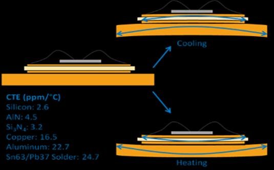
The coefficient of thermal expansion (CTE) describes dimensional changes with temperature, crucial for matching copper foil and substrate to avoid warpage or stress. In high-frequency PCB fabrication, CTE mismatch causes microcracks in vias or pads, especially after reflow soldering. Z-axis CTE, typically 50-70 ppm/°C for reliable materials, ensures interlayer integrity in multilayers. Engineers select materials with CTE close to copper's 17 ppm/°C in the X-Y plane for flatness.
Mechanical stability extends to modulus and peel strength, influencing handling during fabrication. Low moisture absorption complements CTE control by preventing hygroscopic swelling. Standards like IPC-TM-650 2.4.41 for CTE measurement validate material suitability. Balancing CTE with other properties prevents failures in thermal cycling environments.
Additional Considerations in PCB Material Selection
Beyond core electrical and thermal traits, engineers assess moisture absorption, as high levels increase Dk and Df, exacerbating losses. Materials with absorption below 0.1% maintain consistency in humid conditions. Chemical resistance to etching solutions and solder masks affects fabrication yields. Cost and lead times influence scalability, particularly for prototype-to-production transitions.
Fabrication-specific factors include weave style in glass-reinforced materials, which can cause signal skew in high-speed lines. Low-skew constructions minimize this effect. Surface roughness impacts skin effect losses at high frequencies, favoring smoother copper treatments. Integrating these into a holistic evaluation ensures optimal high-frequency PCB fabrication outcomes.
Best Practices for Selecting the Right PCB Material
Begin with defining application requirements, including frequency range, power levels, and environmental exposures. Compile a shortlist of materials based on Dk, Df, thermal conductivity, and CTE targets. Request datasheets and verify properties via independent testing per IPC-TM-650 procedures. Simulate stackups to predict impedance and loss using field solvers.
Collaborate with fabricators early to confirm process compatibility, such as laser drilling for blind vias. Prototype small panels to validate warpage, signal integrity, and thermal performance. Conduct accelerated life tests simulating operational stresses. Document trade-offs in a selection matrix for team review.
Prioritize suppliers adhering to IPC-6012 performance specs for rigid boards, ensuring traceability. Iterate based on test results, refining for volume fabrication. This structured approach minimizes risks in high-frequency PCB fabrication.
Common Challenges and Troubleshooting Insights
One frequent issue is signal loss exceeding predictions due to unaccounted Df rise at higher frequencies. Troubleshooting involves remeasuring Df across the full band and selecting lower-loss alternatives. Warpage from CTE mismatch manifests post-lamination; mitigate with symmetric stackups and controlled cure profiles. Thermal runaway in power sections requires fillers boosting conductivity without spiking Dk.
Fabrication defects like caul-induced voids stem from poor material flow; opt for resin systems with optimized viscosity. Inconsistent Dk from batch variations demands qualified suppliers with tight specs. Electric engineers resolve these by correlating fab data with material properties, enhancing future selections.
Conclusion
Selecting the right PCB material for high-frequency PCB fabrication demands a balanced evaluation of dielectric constant, thermal conductivity, coefficient of thermal expansion, and supporting properties. Engineers achieve superior performance by leveraging standardized test methods and best practices tailored to application needs. Prioritizing low-loss, thermally stable materials ensures signal integrity and reliability across demanding environments. Implementing a systematic selection process reduces risks, optimizes costs, and accelerates time-to-market. With factory-driven insights, teams can fabricate PCBs that excel in telecommunications, radar, and beyond.
FAQs
Q1: What role does dielectric constant play in high-frequency PCB fabrication?
A1: The dielectric constant determines signal speed and impedance control in high-frequency PCB fabrication. Lower Dk values reduce propagation delay, essential for maintaining phase alignment in RF circuits. Engineers select materials with stable Dk across frequencies to avoid distortion. Testing per industry methods confirms suitability for specific bandwidths.
Q2: How does thermal conductivity affect PCB material choices?
A2: Thermal conductivity in PCB material ensures efficient heat dissipation in high-power high-frequency applications. Higher values prevent hotspots that degrade dielectric properties or cause failures. Balance it with low Dk to avoid compromising signal integrity. Fabrication processes benefit from uniform heat transfer during lamination and assembly.
Q3: Why is coefficient of thermal expansion critical for high-frequency PCBs?
A3: Coefficient of thermal expansion mismatch leads to warpage and via failures in high-frequency PCB fabrication. Matching CTE between layers and copper maintains mechanical integrity under thermal stress. Z-axis control prevents delamination in multilayers. Select materials with validated CTE data for reliable performance.
Q4: What standards guide PCB material evaluation for high frequencies?
A4: Standards like IPC-TM-650 provide test methods for dielectric constant, dissipation factor, and CTE in high-frequency PCB fabrication. They ensure consistent characterization across suppliers. Adhering to these supports quality control and performance verification. Factory teams use them for qualification.
References
IPC-TM-650 — Test Methods Manual. IPC, 2020
IPC-6012E — Qualification and Performance Specification for Rigid Printed Boards. IPC, 2017
IPC-4101E — Specification for Base Materials for Rigid and Multilayer Printed Boards. IPC, 2017