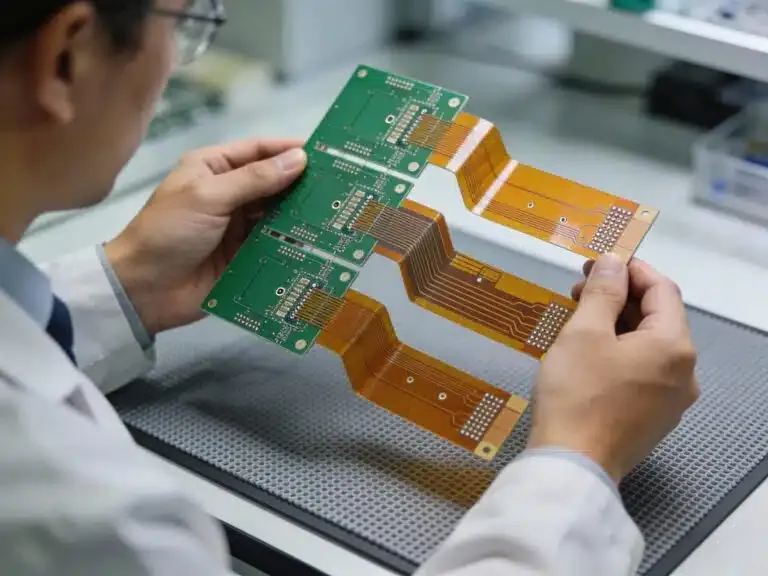
What is PCB Form Factor, and Why Does It Matter for Design?
Before delving into the specifics of mounting techniques, it's essential to grasp the concept of PCB form factor. This term refers to the physical dimensions, shape, and overall arrangement of a printed circuit board, which critically determines how it integrates into a device or its protective enclosure. Selecting an appropriate form factor ensures mechanical compatibility with your application and simplifies the subsequent mounting process.
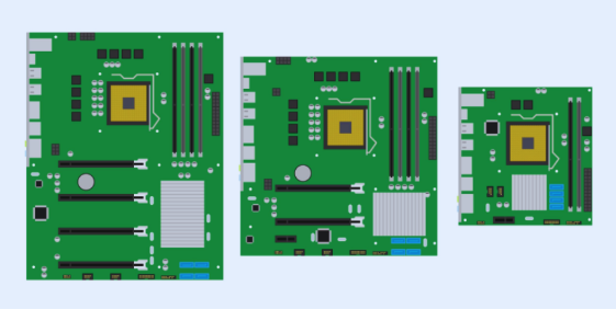
Common PCB form factors include:
● ATX: Frequently utilized in desktop computers, typically measuring 12 x 9.6 inches (305 x 244 mm).
● Micro-ATX: A more compact variation, at 9.6 x 9.6 inches (244 x 244 mm), often preferred for smaller system builds.
● Mini-ITX: An even smaller standard, measuring 6.7 x 6.7 inches (170 x 170 mm), commonly found in small form factor personal computers.
● Custom Sizes: Boards specifically tailored for unique applications like wearables or IoT devices, which often necessitate bespoke mounting solutions.
The process of choosing a form factor involves a careful assessment of space constraints, component placement strategies, and thermal management considerations. For example, a larger PCB might offer ample space for component arrangement but could introduce complexities in enclosure design. It is paramount to always align the chosen form factor with both the mechanical and electrical requirements of your specific project.
The Critical Importance of Proper PCB Mounting
Effective PCB mounting is fundamental to ensuring the long-term operational integrity and reliability of electronic devices. Without a secure mounting strategy, types of PCBs are vulnerable to various detrimental issues, including mechanical stress, damage from vibration, or inadequate thermal dissipation, all of which can ultimately lead to premature device failures. Conversely, robust mounting safeguards against electrical short circuits, preserves signal integrity—a particularly vital aspect in high-frequency applications where impedance mismatches can severely degrade performance (e.g., maintaining a precise 50-ohm impedance for RF signals)—and enhances overall operational safety.
Let's now explore the core elements of PCB mounting, focusing on the hardware involved, various mounting methods, and key design considerations.
Exploring Diverse PCB Mounting Methods
There are several effective PCB mounting methods available, each best suited for different types of applications and environments. Below, we'll examine the most common techniques employed for securely installing a PCB within an enclosure or chassis.
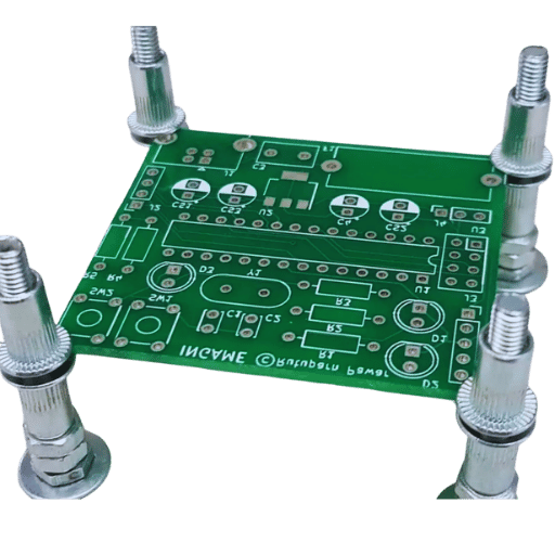
Screws with Standoffs for Robust Support
Utilizing screws in conjunction with standoffs represents one of the most reliable PCB mounting methods. Standoffs are small, rigid spacers designed to elevate the PCB above the mounting surface, effectively preventing electrical short circuits and facilitating crucial airflow for cooling. These components are typically manufactured from materials such as metal (e.g., brass or aluminum) or nylon and are available in various heights, commonly ranging from 0.125 inches (3.18 mm) to over 1 inch (25.4 mm).
The installation process typically involves:
● Drilling precise mounting holes in the PCB, usually 0.125 inches (3.18 mm) in diameter, to match the chosen standoff thread size (e.g., M3 or 4-40).
● Attaching the standoffs securely to the enclosure or chassis.
● Positioning the PCB over the installed standoffs and fastening it with appropriate screws.
This method is particularly well-suited for industrial equipment where exceptional durability and stability are paramount. However, it necessitates meticulous precision in hole placement during the initial PCB design phase.
Quick-Assembly Solutions: Snap-In Clips and Adhesive Pads
Snap-in plastic clips offer a tool-free mounting solution, making them ideal for rapid assembly processes or prototyping. These lightweight, cost-effective plastic holders simply clip onto the PCB edges or pass through designated mounting holes, securing the board in place. While convenient, they are generally less robust than screw-based methods, making them more appropriate for environments with minimal vibration.
Adhesive pads provide a straightforward mounting approach, using double-sided tape or specialized glue to affix the PCB directly to a surface. This method is simple and effective for lightweight boards in constrained spaces. However, it is not recommended for applications involving high heat or significant vibration, as adhesives can degrade over time and lose their structural integrity.
Modular and Industrial Mounting: Rail Systems
DIN rail systems are a prevalent mounting solution in industrial control systems. Here, the PCB is housed within a specialized module that clips securely onto a standardized rail, allowing for effortless installation and removal. This method is exceptionally good for modular designs that require easy interchangeability but may necessitate additional considerations during the enclosure design phase.
Choosing the Right PCB Mounting Hardware
The selection of appropriate PCB mounting hardware is as crucial as the chosen mounting method itself. Here’s a detailed overview of common hardware options and their typical applications.
Screws, Nuts, Standoffs, and Clips
Screws and nuts are commonly fabricated from materials like stainless steel or brass for their corrosion resistance. Standard thread sizes include M2, M3, or 4-40, with lengths varying based on the PCB thickness and standoff height. Torque specifications are critically important to prevent over-tightening, which can lead to PCB damage; a typical torque value for M3 screws on a PCB is 0.5-0.6 Nm.
As previously discussed, standoffs and spacers are essential for preventing electrical shorts and improving airflow beneath the PCB. Key considerations when selecting standoffs include:
● Material: Choose metal for grounding purposes or nylon for electrical insulation.
● Height: Ensure adequate clearance for components positioned underneath the PCB (e.g., 0.25 inches or 6.35 mm for small capacitors).
● Thread Size: Must precisely match the screws for a secure and stable fastening.
Mounting clips and brackets provide supplementary support, particularly beneficial for larger PCBs. These can be custom-designed to conform to specific board shapes, ensuring a snug and secure fit within the designated enclosure.
Crucial Factors for PCB Standoff Selection
Making the correct PCB standoff selection is pivotal to the success and integrity of your design. Here are the primary factors to meticulously evaluate:
● Height: Opt for a height that provides ample clearance for both components and effective heat dissipation. For example, a PCB populated with tall electrolytic capacitors might necessitate a 0.5-inch (12.7 mm) standoff.
● Material: Select conductive standoffs (e.g., brass) if electrical grounding of the PCB to the enclosure is required, or insulating materials (e.g., nylon) to prevent unwanted short circuits.
● Load Capacity: Verify that the chosen standoff can adequately support the PCB’s weight, a particularly important consideration in environments subject to significant vibration.
● Environment: For applications in outdoor or harsh conditions, choose corrosion-resistant materials such as stainless steel.
By carefully aligning your standoff choices with your specific design requirements, you can effectively circumvent common issues such as board flexing or insufficient cooling.
Designing the PCB Enclosure: A Protective Shell
A thoughtfully designed enclosure does more than just shield the PCB from environmental contaminants like dust and moisture, as well as physical damage; it also plays an integral role in the mounting process and thermal management. Here’s a strategic approach to effective PCB enclosure design:
Enclosure Materials, Size, and Mounting
Material selection for enclosures typically involves plastics (e.g., ABS or polycarbonate) for lightweight applications, or metals (e.g., aluminum) for more rugged environments. Metal enclosures also offer the added benefit of electromagnetic interference (EMI) shielding, which is critical for high-frequency circuits operating at 2.4 GHz or above.
When considering size and fit, ensure the enclosure is marginally larger than the PCB itself. This additional space is necessary to comfortably accommodate all mounting hardware and associated wiring. For instance, leaving a minimum of 0.1 inches (2.54 mm) of clearance on all sides can prevent undue stress on the board.
For mounting points, it is best practice to integrate these directly into the enclosure design. This can include features such as bosses for screw mounting or dedicated slots for snap-in clips, which collectively simplify the assembly process and ensure a secure fit.
Ventilation and Cooling Strategies
For ventilation and cooling, it is crucial to design vents or strategically placed slots to facilitate proper airflow, especially if the PCB generates significant heat (e.g., power supply circuits dissipating 10W or more). In high-power applications, the incorporation of cooling fans or heat sinks may become absolutely necessary to prevent thermal damage.
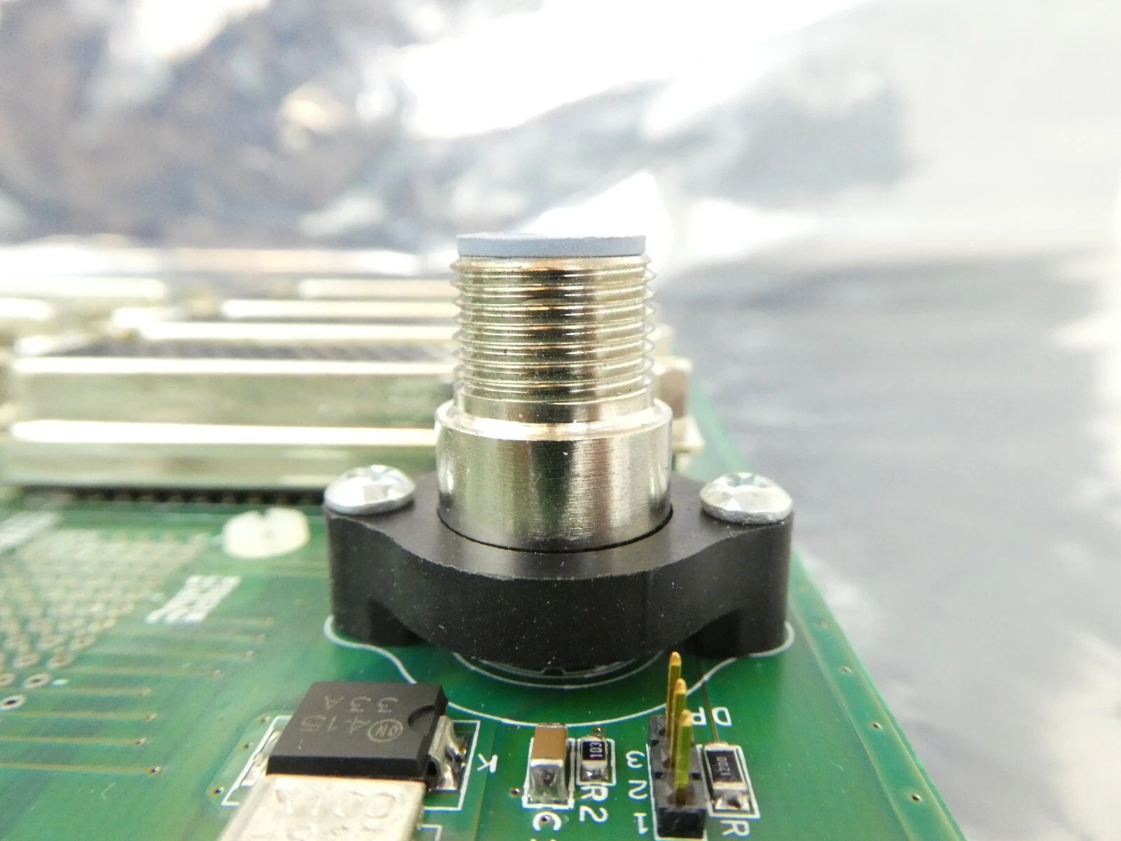
Vibration-Resistant PCB Mounting: Ensuring Long-Term Durability
In challenging applications, such as automotive systems or industrial machinery, persistent vibration can cause mounting hardware to loosen or even damage critical components. Implementing vibration-resistant PCB mounting techniques is therefore essential for ensuring the long-term reliability of devices in such environments.
Techniques for Enhanced Vibration Resistance
● Utilize Locking Hardware: Opt for screws paired with locking washers, or apply thread-locking compounds to prevent fasteners from loosening under continuous vibration. Nylon-insert lock nuts are also highly effective, maintaining their grip even when subjected to constant mechanical oscillation.
● Integrate Rubber or Silicone Dampers: Incorporate rubber grommets or silicone pads between the PCB and its mounting surface. These dampers are designed to absorb vibrations, and industrial testing typically shows they can reduce mechanical stress on the board by up to 50%.
● Reinforce Mounting Points: For high-vibration settings, employ additional mounting points or reinforce existing brackets to evenly distribute stress across the PCB. Avoid designs that concentrate mounts solely at the corners, as this can induce undesirable flexing in the board's central area.
● Secure Component Placement: Ensure that heavier components, such as transformers, are securely fastened using adhesive or supplementary mechanical fasteners. This is particularly vital to prevent them from detaching during prolonged exposure to vibration, especially for boards experiencing frequencies between 10-100 Hz.
Best Practices for PCB Mounting and Design
To conclude, here are some overarching best practices to ensure your PCB mounting strategy is both highly effective and consistently reliable:
● Plan Mounting Early: Incorporate mounting hole locations and standoff placements into the very initial stages of your PCB layout design to avoid costly redesigns later.
● Test for Stress: Conduct simulations or physical tests under anticipated vibration and thermal conditions to identify and address any weak points in your mounting setup proactively.
● Consider Accessibility: Design your mounting system such that screws or clips remain easily accessible, facilitating future maintenance, upgrades, or repairs.
● Follow Industry Standards: Adhere strictly to industry standards, such as IPC-A-610, which outlines acceptable mounting practices, thereby ensuring both the quality and safety of your assemblies.
Conclusion: Mastering PCB Form Factor and Mounting
A thorough understanding of PCB form factor and effective mounting techniques is absolutely vital for developing robust and highly efficient electronic designs, especially when working with advanced solutions such as HDI PCB. From the initial selection of appropriate mounting hardware to the meticulous design of a protective enclosure, every single step plays a crucial role in guaranteeing that your PCB will perform reliably across a diverse range of operational conditions. By focusing on critical details such as precise standoff selection and implementing robust vibration-resistant mounting strategies, you can effectively avoid common design pitfalls and significantly extend the lifespan of your electronic assemblies.
Whether your current project involves a small-scale prototype or a complex industrial system, applying the comprehensive insights provided in this guide will undoubtedly help you achieve secure, professional, and high-performing PCB installations. Keep these essential tips in mind as you embark on the design and mounting of your next circuit board, and you will be well-equipped for success.