Introduction
In the realm of PCB design, the choice of substrate material forms the foundation of performance, reliability, and manufacturability, especially for double-sided PCBs. These boards, featuring conductive traces on both sides connected via plated through-holes, demand substrates that balance electrical insulation, mechanical stability, and thermal resilience. Double-sided PCB materials directly influence signal integrity, heat dissipation, and long-term durability under operational stresses. Electrical engineers must prioritize PCB substrate selection early in the design process to avoid costly revisions or failures in assembly. This article explores key PCB material properties, common options like FR-4 PCB, and structured PCB design considerations to guide optimal choices. By understanding these elements, designers can ensure their boards meet application requirements efficiently.
Understanding PCB Substrates in Double-Sided Boards
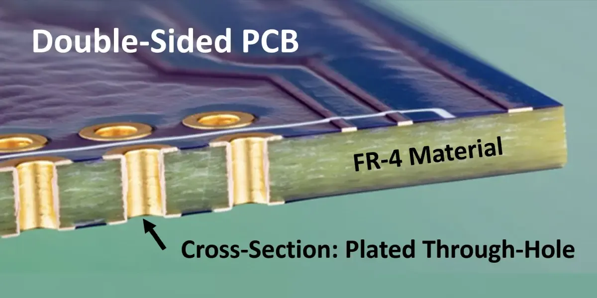
A PCB substrate serves as the insulating core that supports copper traces and components, typically composed of a reinforcing fiber impregnated with resin. In double-sided PCBs, the substrate must withstand lamination pressures, drilling for vias, and soldering temperatures without delaminating or warping. FR-4 PCB, the industry standard, consists of woven glass fabric reinforced with epoxy resin, offering a robust base for most applications. Why does this matter? Poor substrate selection leads to issues like trace cracking, via failures, or impedance mismatches, compromising board functionality. Engineers evaluate substrates based on their ability to maintain dimensional stability across manufacturing and service life cycles.
The relevance intensifies for double-sided designs, where copper on both sides amplifies thermal expansion mismatches. Substrates dictate how well the board handles reflow soldering, mechanical shocks, and environmental exposures. Standard specifications like IPC-4101 outline requirements for base materials, ensuring consistency in resin content and glass transition behavior. Selecting the right double-sided PCB materials prevents common pitfalls, such as bow and twist exceeding acceptable limits during assembly. Ultimately, informed PCB substrate selection aligns material properties with design goals, enhancing yield rates and product lifespan.
Key PCB Material Properties for Double-Sided Applications
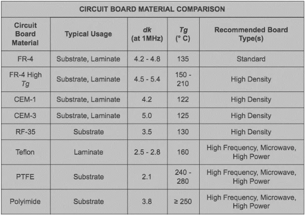
PCB material properties fall into electrical, thermal, and mechanical categories, each critical for double-sided PCB performance. Electrical properties include dielectric constant (Dk) and dissipation factor (Df), which affect signal propagation speed and losses. For double-sided boards with moderate frequencies, low Df minimizes attenuation in traces routed across layers. Thermal properties, such as glass transition temperature (Tg) and coefficient of thermal expansion (CTE), determine stability during soldering peaks above 250°C. Mechanical attributes like tensile strength and flexural modulus resist handling stresses and support via integrity.
Consider electrical performance first. Substrates with stable Dk values ensure predictable impedance in transmission lines, vital for double-sided layouts with ground planes on opposing sides. Variations in resin-glass ratio influence these metrics, requiring datasheets for precise matching. Thermal resilience prevents softening or cracking; higher Tg materials maintain rigidity post-solder reflow. CTE alignment between substrate and copper foil reduces stress at vias, a frequent failure point in double-sided PCBs. Mechanical robustness counters warpage from asymmetric copper distribution, common in these simpler multilayer designs.
IPC-6012 provides qualification criteria for rigid boards, including double-sided types, emphasizing these properties through tests like thermal cycling. Engineers must weigh trade-offs: cost-effective options excel in benign environments, while demanding apps need enhanced grades. Water absorption impacts insulation resistance over time, particularly in humid conditions. By systematically assessing these PCB material properties, designers mitigate risks in PCB substrate selection.
FR-4 PCB: The Go-To Substrate and Its Characteristics
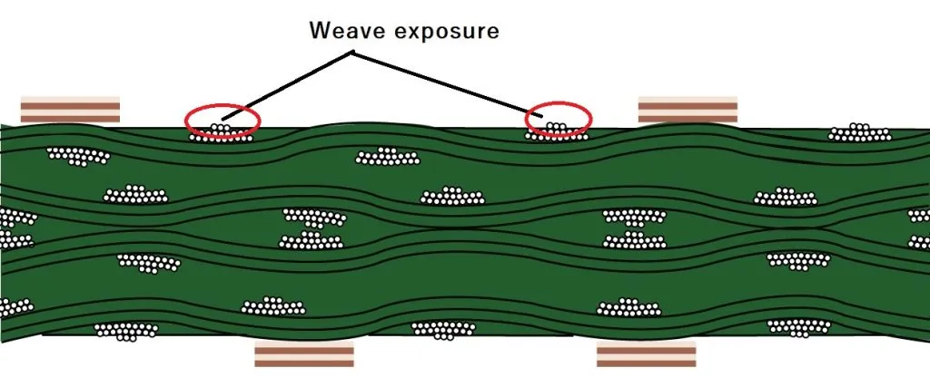
FR-4 PCB dominates double-sided applications due to its versatile properties and availability. This flame-retardant composite features E-glass cloth woven tightly with brominated epoxy resin, achieving vertical burn resistance per established grades. Standard FR-4 offers Tg around 130°C to 140°C, sufficient for most lead-free assemblies. Its CTE matches copper closely in the x-y plane, minimizing planar warpage. Electrical insulation remains reliable up to several gigahertz, with low Df for consumer electronics.
For double-sided PCBs, FR-4 supports thicknesses from 0.4mm to 3.2mm, accommodating varied copper weights. Enhanced FR-4 variants provide higher Tg above 170°C for automotive or industrial uses, resisting multiple reflow cycles. Mechanical strength allows punching or routing without microcracks. However, its thermal conductivity limits high-power dissipation, necessitating vias or heat sinks. FR-4 PCB proves cost-effective for prototypes to production, aligning with PCB design considerations for volume manufacturing.
Alternatives to FR-4 for Specialized Double-Sided PCBs
While FR-4 suits general purposes, alternatives address specific challenges in double-sided PCB materials. Composite epoxy materials (CEM-1 or CEM-3) offer lower cost with paper or glass reinforcement, ideal for low-end consumer boards. CEM-3 provides better punchability and flame retardancy than phenolic papers, though with slightly higher CTE. Polyimide substrates excel in high-temperature environments above 200°C, maintaining flexibility and low outgassing for aerospace. These deliver superior Tg over 250°C but at higher expense.
High-frequency laminates with ceramic or PTFE fillers reduce Dk and Df for RF double-sided designs, though drilling poses challenges. Metal-clad substrates enhance thermal management for power electronics, dissipating heat via the core. Selection hinges on application: FR-4 for balanced performance, alternatives for extremes. PCB substrate selection involves datasheets verifying compliance with process flows.
PCB Design Considerations for Substrate Selection
Effective PCB substrate selection integrates design constraints like board size, layer count, and operating frequency. For double-sided PCBs, simulate CTE mismatches using finite element analysis to predict warpage. Copper balance across sides prevents bowing; aim for 50% coverage per side. Thermal vias and ground pours leverage substrate properties for heat spreading. Signal integrity tools model Dk effects on trace delays.
Manufacturing factors influence choices: drill bit wear on glass-heavy substrates affects via quality. Lamination cycles demand consistent resin flow per IPC standards. Environmental specs guide moisture sensitivity; low-absorbency materials suit humid exposures. Cost-volume analysis weighs FR-4 economy against premium options. Iterative prototyping validates assumptions.
Best practices include specifying slash sheets from IPC-4101 for precise grades, like /101 for standard FR-4. Collaborate with fabricators on stackup drawings detailing thickness and Tg. Qualification testing per board performance specs confirms reliability. These PCB design considerations ensure substrates enhance rather than hinder functionality.
Common Challenges in Substrate Performance and Mitigation
Double-sided PCBs face substrate-related issues like delamination from moisture entrapment or thermal shock. Pre-baking boards per handling guidelines expels absorbed water before reflow. Warpage arises from asymmetric layouts; symmetric patterning or balanced cores counters it. Via barrel cracking stems from z-axis CTE mismatch; select low-CTE grades.
High-frequency losses demand low-Df substrates, verified via TDR measurements. Mechanical flexing risks microcracks; reinforce with thicker cores. Troubleshooting involves root-cause analysis: inspect cross-sections for resin voids. Proactive material qualification averts field failures.
Conclusion
Selecting the right substrate profoundly impacts double-sided PCB reliability and performance. FR-4 PCB remains the benchmark for its balanced PCB material properties, while alternatives target niche demands. Key factors like thermal stability, electrical characteristics, and mechanical integrity guide PCB substrate selection. Adhering to structured PCB design considerations and industry standards optimizes outcomes. Engineers who prioritize these elements deliver robust, manufacturable boards that excel in real-world applications.
FAQs
Q1: What are the primary PCB material properties to evaluate for double-sided PCB materials?
A1: Electrical engineers focus on dielectric constant, dissipation factor, glass transition temperature, CTE, and mechanical strength. These ensure signal integrity, thermal resilience, and dimensional stability during assembly and operation. Low Df minimizes losses, while matched CTE prevents via failures. Always cross-reference with application requirements for optimal PCB substrate selection.
Q2: Why is FR-4 PCB the most common choice for double-sided boards?
A2: FR-4 offers a cost-effective blend of flame retardancy, high mechanical strength, and reliable electrical insulation suitable for most frequencies. Its process compatibility supports standard drilling, plating, and soldering. For moderate thermal demands, standard grades suffice without premium costs. PCB design considerations favor FR-4 for high-volume production.
Q3: How do thermal properties influence PCB substrate selection?
A3: Tg determines softening resistance during reflow, while CTE alignment avoids stress cracks at copper interfaces. Low thermal conductivity suits low-power apps but requires aids for dissipation. Engineers select based on peak temperatures and cycles, ensuring compliance with qualification specs.
Q4: What PCB design considerations prevent warpage in double-sided PCBs?
A4: Balance copper distribution symmetrically and choose substrates with low z-axis CTE. Simulate thermal loads early and specify thicknesses per stackup needs. Fabrication guidelines like controlled lamination minimize bow and twist.
References
IPC-4101E — Specification for Base Materials for Rigid and Multilayer Printed Boards. IPC, 2017
IPC-6012E — Qualification and Performance Specification for Rigid Printed Boards. IPC, 2020


