Introduction
Metal core PCBs represent a critical advancement in PCB materials for applications demanding superior thermal management. These boards integrate a metal substrate beneath the standard copper circuit layers, enabling efficient heat dissipation from power components. Electric engineers often specify metal core PCBs in high-density designs such as power supplies, LED lighting, and automotive electronics where standard FR4 substrates fall short. Selecting the appropriate metal, whether aluminum, copper, or specialized alloys, directly impacts performance, reliability, and overall system cost. This article explores key PCB materials for metal core construction, focusing on thermal conductivity, cost trade-offs, and practical selection criteria aligned with manufacturing realities.
What Is a Metal Core PCB and Why Does It Matter?
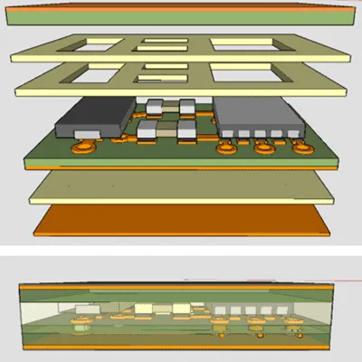
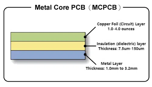
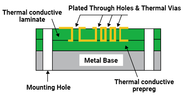
A metal core PCB consists of a thermally conductive metal base, typically 1 to 2 mm thick, bonded to a dielectric layer with high thermal conductivity, followed by copper traces and solder mask. The metal core acts as a heat spreader, channeling heat away from sensitive components to the board edges or attached heatsinks. Unlike traditional FR4 PCBs, which have low thermal conductivity around 0.3 W/mK, metal core variants achieve dielectric thermal conductivity from 1.0 to 4.0 W/mK or higher, dramatically improving heat transfer.
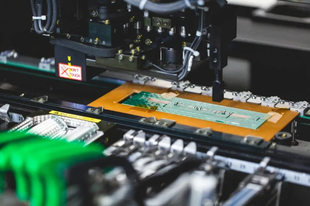
This design matters in electric engineering because excessive heat leads to component degradation, reduced lifespan, and failure in high-power applications. For instance, in power inverters or RF amplifiers, poor thermal management can exceed junction temperatures, violating reliability standards. Factory production of metal core PCBs requires precise control over lamination and etching to maintain flatness and insulation integrity. Engineers benefit from these boards by minimizing external cooling needs, reducing system weight, and enhancing overall efficiency.
Technical Principles of Metal Core Materials
The core principle behind metal core PCBs lies in the thermal conductivity of the base metal, which facilitates lateral heat spreading before vertical transfer through the dielectric. Aluminum, the most common choice, offers thermal conductivity ranging from 138 to 238 W/mK depending on alloy grade, providing adequate performance for many applications. Copper excels with approximately 400 W/mK, nearly double that of aluminum, enabling faster heat dissipation in extreme conditions. Alloys, such as aluminum-copper composites or stainless steel variants, bridge gaps in properties like strength or corrosion resistance but are less prevalent due to processing complexities.
Thermal performance also depends on the coefficient of thermal expansion (CTE) matching between the metal core, dielectric, and copper layers to prevent warpage during thermal cycling. IPC-2221 guidelines emphasize evaluating these material interactions during design to ensure mechanical stability. In manufacturing, the metal base influences drillability and plating adhesion, with softer aluminum requiring careful tooling to avoid burring. Electric engineers must model heat flow using finite element analysis, considering boundary conditions like ambient temperature and airflow.
Density plays a role too, as copper's 8.96 g/cm3 contrasts with aluminum's lighter profile around 2.7 g/cm3, affecting portability in mobile or aerospace designs. Factory insights reveal that metal core thickness standardization, often 1.5 mm, optimizes yield while balancing rigidity and thermal mass.
Comparing Key Metals: Aluminum, Copper, and Alloys
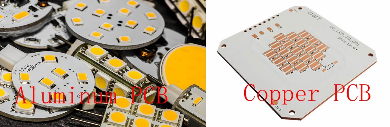
Aluminum dominates metal core PCB production due to its balance of thermal conductivity, low cost, and ease of machining. It suits general high-power LEDs and power modules where heat loads do not exceed moderate levels. However, its lower conductivity compared to copper limits use in ultra-high-density applications. Manufacturers prefer aluminum for its corrosion resistance with proper surface treatments and minimal warpage in standard processes.
Copper core PCBs deliver unmatched thermal performance, ideal for electric vehicle inverters or high-frequency power converters demanding rapid heat rejection. The higher conductivity reduces thermal resistance by up to 50% versus aluminum in direct pad-mounted components. Drawbacks include elevated cost, roughly 2-3 times that of aluminum, and increased weight, which complicates handling in assembly lines. Despite this, copper's superior current-carrying capacity enhances reliability under sustained loads.
Alloys offer tailored solutions, such as high-strength aluminum alloys for rugged environments or copper-invar composites for CTE control in precision RF boards. These PCB materials provide thermal conductivity between 200-350 W/mK while improving tensile strength or reducing expansion mismatch. Factory-driven selection favors alloys when standard metals fail dimensional stability tests per IPC-6012 specifications for rigid boards. Engineers weigh these against higher fabrication costs and limited supplier availability.
- Thermal Conductivity (W/mK): Aluminum 138-238; Copper ~400; Alloys 200-350
- Density (g/cm3): Aluminum ~2.7; Copper ~8.96; Alloys vary
- Relative Cost: Aluminum low; Copper high; Alloys medium-high
- Common Applications: Aluminum for LEDs and power supplies; Copper for EV inverters and RF; Alloys for rugged and precision needs
Practical Best Practices for Material Selection
Choosing the right metal starts with assessing power dissipation and junction temperature limits in your design. Calculate required thermal resistance using theta-JC values and simulate board-level spreading with tools compliant to JEDEC JESD51 thermal characterization standards. For cost-sensitive projects under 50W per component, aluminum suffices; escalate to copper for over 100W densities. Always specify dielectric thickness, typically 100-150 microns, to balance insulation and conductivity.
In manufacturing, verify metal core flatness post-lamination to meet IPC-A-600 acceptability criteria, as bow and twist exceed 0.75% in class 2 boards. Opt for single-sided or double-sided layouts to simplify via-in-pad thermal paths, avoiding blind vias that complicate drilling on hard metals. Procurement teams should request material datasheets confirming purity and alloy composition to predict CTE behavior.
Test prototypes under real operating conditions, monitoring hotspots with infrared thermography. Factory experience shows annealing copper cores reduces internal stresses, improving yield. Balance total PCB materials cost against lifecycle savings from enhanced reliability.
Troubleshooting Common Challenges
Warpage emerges as a frequent issue in metal core PCBs due to CTE mismatches during reflow soldering. Aluminum cores, with CTE around 22 ppm/°C, pair well with standard dielectrics, but copper's 17 ppm/°C requires low-CTE fillers. Mitigate by symmetric stackups and controlled cooling ramps per manufacturing protocols.
Delamination at the dielectric-metal interface arises from poor bonding under humidity. Select dielectrics with proven adhesion strength and bake boards pre-assembly. High-power designs may suffer from hotspot localization if copper pour areas lack stitching vias; distribute heat sources evenly.
Cost overruns occur when overlooking tooling for copper's ductility. Engineers should collaborate early with fabricators to define panel sizes and routing tabs suited to the metal.
Conclusion
Selecting metal core PCB materials hinges on aligning thermal conductivity, cost, and mechanical properties with application demands. Aluminum offers economical versatility for most electric engineering needs, while copper provides premium performance at a premium price. Alloys fill niche roles requiring optimized traits. Adhering to standards like IPC-2221 ensures designs translate reliably to production. By prioritizing simulation, testing, and factory insights, engineers achieve robust thermal management without excess expenditure.
FAQs
Q1: What factors determine thermal conductivity in metal core PCBs?
A1: Thermal conductivity depends on the base metal, dielectric layer, and thickness. Aluminum provides 138-238 W/mK, copper around 400 W/mK, with dielectrics at 1-4 W/mK transferring heat vertically. Engineers must model paths considering vias and pours for optimal dissipation in high-power metal core PCB designs. Factory standards ensure consistent performance.
Q2: How does cost compare between aluminum and copper for metal core PCBs?
A2: Aluminum cores keep costs low due to material abundance and simple processing, ideal for volume production. Copper increases expenses 2-3 times from higher raw material and machining demands. Balance with application needs, as copper's superior thermal conductivity justifies premiums in demanding electric systems. Procurement focuses on total lifecycle economics.
Q3: When should electric engineers choose copper over aluminum in PCB materials?
A3: Opt for copper in applications exceeding 100W dissipation or requiring minimal thermal resistance, like EV power modules. Its 400 W/mK conductivity outperforms aluminum's range, enhancing reliability. Aluminum suits moderate loads with cost savings. Evaluate via thermal simulations per JEDEC guidelines.
Q4: Are there reliable alloys for specialized metal core PCB applications?
A4: Alloys like enhanced aluminum or copper composites offer thermal conductivity of 200-350 W/mK with improved strength or CTE matching. They address challenges in rugged or RF environments where pure metals falter. Manufacturing yields benefit from standardized processes, though availability varies. Select based on precise engineering requirements.
References
IPC-2221 — Generic Standard on Printed Board Design. IPC
IPC-6012E — Qualification and Performance Specification for Rigid Printed Boards. IPC, 2017
IPC-A-600K — Acceptability of Printed Boards. IPC, 2020
JEDEC JESD51-12 — Guidelines for Reporting and Using Electronic Package Thermal Information. JEDEC