Introduction
Laser drilling has become essential in modern PCB manufacturing, particularly for creating precise microvias in high-density interconnect boards. These tiny vias enable denser routing and improved signal integrity in advanced electronics. Optimizing laser drilling parameters directly impacts hole quality, production throughput, and overall board reliability. Key factors such as laser power, drilling frequency, and laser drilling speed must be fine-tuned to balance ablation efficiency with minimal thermal damage. This article explores these parameters in depth, offering factory-driven insights for electric engineers working on PCB manufacturing parameters. By understanding their interactions, engineers can achieve consistent results aligned with industry expectations.
The Role of Laser Drilling in PCB Manufacturing
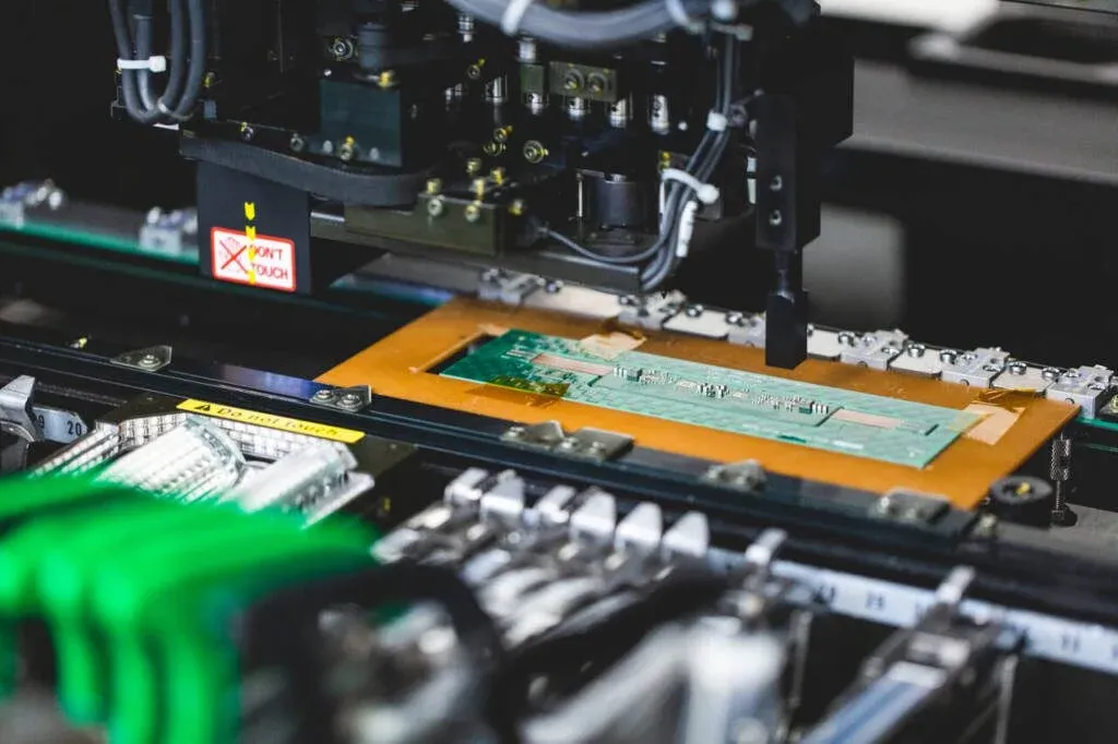
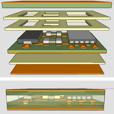
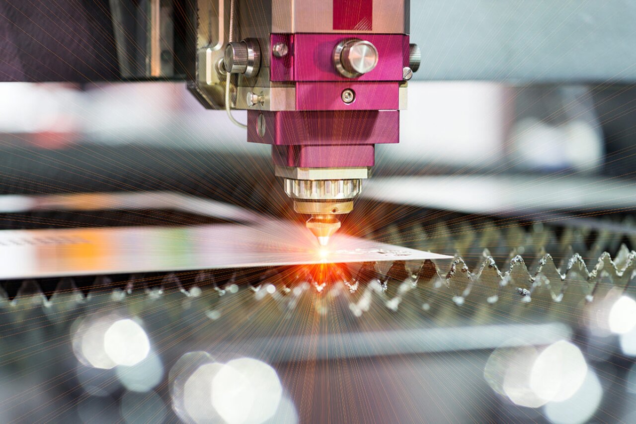
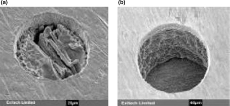
Laser drilling uses ultraviolet lasers to ablate dielectric and copper layers, forming vias as small as 50 microns in diameter. This process supports blind, buried, and through-hole configurations critical for multilayer HDI PCBs. Poorly optimized parameters lead to issues like tapered holes, carbon residue, or enlarged heat-affected zones, compromising plating adhesion and electrical performance. In high-volume production, laser drilling parameters determine cycle times and yield rates, making optimization a core competency in factories. Electric engineers must consider material properties, such as resin type and copper thickness, when setting these values. Ultimately, effective laser drilling ensures compliance with quality benchmarks and supports miniaturization trends in electronics.
Fundamental Principles of Laser Ablation
Laser ablation in PCBs relies on photon energy breaking molecular bonds in the target material without excessive heat buildup. Ultraviolet lasers, typically operating at 355 nm wavelength, provide high absorption in common dielectrics like FR-4 or high-Tg resins. The process involves vaporizing material in pulses, creating a conical hole shape that requires parameter adjustments for straight sidewalls. Power delivers the energy per pulse, frequency controls pulse repetition, and speed governs the beam's traversal path. These elements interact dynamically; for instance, high power with low speed amplifies thermal effects. Engineers analyze ablation thresholds, often around 1-5 J/cm2 depending on material, to predict drilling behavior.
Thermal management remains crucial, as excessive heat can delaminate layers or form microcracks. Pulse duration, usually in the nanosecond range, influences the plasma plume and debris ejection. Factory processes incorporate assist gases like nitrogen to clear residue and cool the site. Understanding these mechanisms allows precise control over entrance and exit diameters. Consistent ablation rates, measured in microns per pulse, form the basis for parameter selection. This technical foundation guides optimization efforts in production environments.
Laser Power Optimization: Balancing Energy and Precision
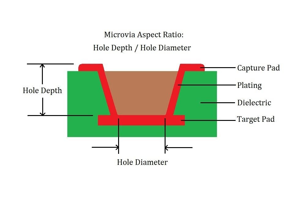
Laser power, expressed in watts as average or peak values, dictates the ablation depth per pulse. Higher power accelerates material removal, boosting throughput in high-volume PCB lines, but risks enlarging the heat-affected zone and causing rough hole walls. Optimization involves starting with baseline values suited to stack-up thickness, then incrementally adjusting while monitoring via profiles. For thin dielectrics, moderate power preserves copper integrity around the via pad. Electric engineers use power ramps, gradually increasing during drilling, to minimize taper from entrance to exit. This approach ensures uniform aspect ratios, typically up to 1:1 for microvias.
Material interactions further complicate power settings; copper reflects more laser energy than resin, requiring higher pulses to penetrate foil layers. Overpowering leads to molten copper spatter, contaminating adjacent surfaces and complicating desmear processes. Factories employ real-time power monitoring to maintain stability amid laser diode aging. According to IPC-6012E, vias must exhibit clean, smooth walls post-plating, underscoring the need for laser power optimization. Engineers correlate power with metrology data from optical profilers to validate settings. Fine-tuning power not only enhances quality but also extends laser head life in continuous operations.
Drilling Frequency: Pulse Repetition and Overlap Dynamics
Drilling frequency, or pulse repetition rate in kHz, determines how rapidly the laser delivers energy to the site. Higher frequencies increase drilling speed by overlapping pulses, filling the hole volume faster, but excessive overlap generates cumulative heat. Optimal settings depend on beam spot size, usually 20-30 microns, and desired depth; low frequencies suit shallow vias to avoid resonance effects. In stacked vias, frequency adjustments prevent breakthrough inconsistencies across layers. Factories calibrate frequency to match galvo scanner capabilities, ensuring precise beam positioning.
Pulse overlap percentage, ideally 70-90%, influences sidewall smoothness and debris management. Low frequency results in scalloped walls, visible under SEM inspection, while high frequency risks plasma shielding that reduces efficiency. Engineers model frequency impacts using ablation rate equations, factoring in fluence thresholds. This parameter synergizes with power; elevated frequency demands proportional power scaling to sustain depth progression. Production data logs track frequency variations for yield analysis. Mastering drilling frequency elevates PCB manufacturing parameters to support finer pitch designs.
Laser Drilling Speed: Throughput Versus Accuracy Trade-Offs
Laser drilling speed encompasses galvo scan velocity and stage translation rates, measured in mm/s. Faster speeds widen holes due to reduced dwell time per spot, suiting large arrays but compromising depth control in microvias. Slower speeds enable deeper penetration and straighter profiles, essential for high-aspect-ratio features. Optimization balances cycle time with quality; typical speeds range from 100-1000 mm/s based on board complexity. Vectoring paths, like spiral or raster patterns, optimize speed for uniform energy distribution. Factories integrate speed with autofocus systems to handle topography variations.
Inter-layer speed adjustments account for differing ablation rates between dielectric and copper. Excessive speed causes incomplete drilling, leaving resin stubs that fail desmear. Conversely, slow speeds amplify thermal buildup, per IPC-A-600K acceptability criteria for surface finish. Engineers employ speed profiles that accelerate over copper and decelerate in resin. Real-time feedback from vision systems refines these dynamics. Effective laser drilling speed optimization directly correlates with factory output and defect rates.
Parameter Interactions and Optimization Strategies
No single parameter operates in isolation; power, frequency, and speed form a triad influencing overall performance. High power paired with low frequency and moderate speed maximizes depth while controlling heat. Conversely, high frequency and speed with reduced power suit rapid prototyping of shallow vias. Design of experiments, varying one factor at a time, reveals synergies and thresholds. Factories use statistical process control charts to map parameter spaces against key performance indicators like via resistivity and pull strength.
Material stack-up dictates baseline interactions; thicker cores demand higher power and lower speeds. Environmental factors, such as humidity affecting resin ablation, necessitate adaptive tuning. Software simulations predict outcomes, but empirical validation on pilot panels remains standard. Optimization cycles incorporate post-drill inspections, including cross-sectioning per IPC guidelines. This holistic approach minimizes scrap and accelerates ramp-up. Electric engineers benefit from documenting parameter sets for repeatability across shifts.
Best Practices and Troubleshooting in Production
Establish baseline parameters from material data sheets and prior runs, then iterate using factorial designs. Implement closed-loop controls for power stability and beam alignment. Regular laser maintenance, including lens cleaning, sustains performance. For troubleshooting, tapered holes signal power imbalance; increase ramping or reduce speed. Excessive debris points to low frequency; elevate pulses with assist gas flow. Rough walls indicate suboptimal overlap; fine-tune frequency and speed ratios.
Conduct inline metrology after drilling to catch deviations early. Desmear efficacy validates parameter choices, as plasma treatment targets residue from aggressive settings. Yield tracking identifies chronic issues like inconsistent depths, often tied to speed variations. Collaborate with plating teams to ensure via readiness. Adhering to J-STD-001 standards for workmanship reinforces these practices. These factory-driven best practices yield robust PCB manufacturing parameters.
Conclusion
Optimizing laser drilling parameters demands a nuanced understanding of power, frequency, and speed interactions. These elements drive microvia quality, enabling advanced HDI designs while upholding production efficiency. Factory engineers achieve success through systematic tuning, metrology, and standards compliance. Balancing ablation precision with throughput minimizes defects and maximizes reliability. As PCB densities rise, mastering laser power optimization, drilling frequency, and laser drilling speed remains pivotal. Implement these insights to elevate your processes and deliver superior boards.
FAQs
Q1: What are the main laser drilling parameters to optimize in PCB manufacturing?
A1: Laser drilling parameters include power for ablation energy, drilling frequency for pulse rate, and laser drilling speed for scan velocity. Optimizing them ensures clean microvias with minimal taper and heat damage. Factories start with material-specific baselines, using iterative testing to balance quality and throughput. Compliance with IPC standards guides acceptable hole geometries. This approach supports high-yield HDI production for electric engineers.
Q2: How does laser power optimization affect via quality?
A2: Laser power optimization controls depth per pulse and thermal effects in PCB vias. Higher power speeds drilling but risks rough walls and residue if unbalanced. Engineers ramp power for straight profiles and monitor heat-affected zones. Pairing with frequency and speed prevents over-ablation. Factory metrology confirms plating readiness per industry norms. Proper tuning enhances reliability in dense interconnects.
Q3: Why is drilling frequency critical in laser drilling speed?
A3: Drilling frequency sets pulse overlap, directly influencing laser drilling speed and hole smoothness. Higher frequencies accelerate throughput but require power adjustments to avoid heat buildup. Low frequencies suit precision but slow cycles. Optimize for 70-90% overlap to minimize scalloping. Factories log data for consistent PCB manufacturing parameters across runs. This ensures uniform via arrays in multilayer boards.
Q4: What common issues arise from poor laser drilling parameters?
A4: Poor laser drilling parameters cause tapered holes, debris accumulation, or delamination in PCBs. Excessive power enlarges heat zones, while mismatched speed and frequency leaves incomplete drills. Troubleshooting involves parameter recalibration and inspections. Align with IPC-A-600K for acceptability. Electric engineers use process controls to maintain yield. Proactive optimization prevents downstream failures in assembly.
References
IPC-6012E — Qualification and Performance Specification for Rigid Printed Boards. IPC, 2017
IPC-A-600K — Acceptability of Printed Boards. IPC, 2020
J-STD-001H — Requirements for Soldered Electrical and Electronic Assemblies. IPC, 2018