Introduction
Rigid-flex printed circuit boards integrate rigid substrates with flexible sections to enable compact, reliable designs in demanding applications such as aerospace, medical devices, and consumer electronics. Selecting appropriate connectors for these boards is crucial because they must accommodate the unique mechanical and thermal characteristics of the hybrid structure. Poor connector choices can lead to failures from flexing stresses, signal degradation, or assembly complications. This comprehensive guide explores rigid-flex PCB connector types, selection criteria, reliability considerations, and assembly best practices. Engineers can use these insights to optimize performance while adhering to established industry guidelines. By focusing on key factors, designs achieve enhanced durability and functionality.
Understanding Rigid-Flex PCBs and the Importance of Connectors
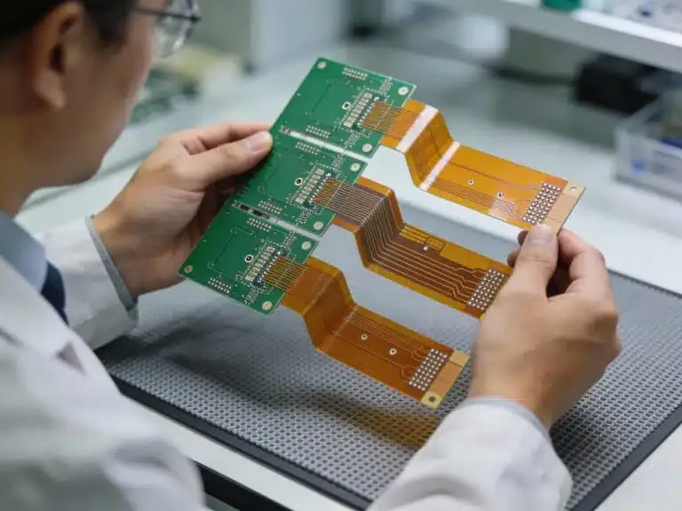
Rigid-flex PCBs consist of rigid multilayer sections typically made from FR-4 materials combined with flexible polyimide layers that allow bending and folding. These boards reduce the need for separate interconnects like cables or wire harnesses, minimizing points of failure in dynamic environments. Connectors serve as the primary interface between the rigid-flex PCB and external systems, such as mating boards, cables, or enclosures. In rigid-flex designs, connectors are predominantly placed on the rigid portions to avoid stressing the flex areas during mating or vibration. Their selection directly impacts overall system reliability, as mismatches in thermal expansion or mechanical compliance can cause delamination or contact issues. Understanding these interactions ensures that rigid-flex PCB connectors support the board's intended motion and environmental exposure.
The role of connectors extends to maintaining signal integrity and power delivery across the hybrid structure. Flexible sections often carry high-speed signals or power traces that terminate at connector pads on rigid zones. Factory-driven insights emphasize evaluating connector compatibility early in the design phase to prevent costly rework. Standards like IPC-2223 provide guidelines for placing connectors away from bend zones, promoting long-term stability. This proactive approach aligns with manufacturing realities where precise tolerances define success.
Rigid-Flex PCB Connector Types
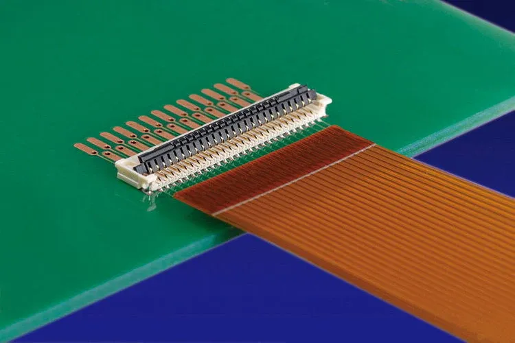
Rigid-flex PCB connector types vary based on application needs, including pitch, height, and mating style. Fine-pitch flexible flat cable (FFC) and flexible printed circuit (FPC) connectors, often with zero insertion force (ZIF) or low insertion force (LIF) mechanisms, suit connections to flex tails extending from the board. These connectors feature clamshell actuators for easy mating and support pitches from 0.3 mm to 1.0 mm, ideal for high-density designs. Board-to-board (BTB) connectors, such as mezzanine or stacking types, enable vertical or parallel interconnections between rigid sections of multiple rigid-flex boards. Wire-to-board (WTB) options provide robust interfaces for external cabling, with locking features to withstand vibration.
Another category includes press-fit connectors that eliminate soldering by compressing contacts into plated-through holes on the rigid substrate. These offer high mechanical retention suitable for high-reliability sectors. Hybrid connectors combine power and signal pins in a single housing, accommodating diverse current requirements. Each type must match the rigid-flex PCB's layer stackup and trace routing to prevent impedance discontinuities. Factory experience shows that selecting the correct subtype early reduces assembly defects.
Key Factors in Rigid-Flex PCB Connector Selection
Rigid-flex PCB connector selection begins with evaluating electrical specifications like current rating, voltage standoff, and contact resistance stability. Designers must consider the operating environment, including temperature range, humidity, and exposure to chemicals, as flex materials like polyimide exhibit different coefficients of thermal expansion than rigid FR-4. Mechanical factors such as mating cycles, insertion force, and retention strength are critical, especially in applications with repeated flexing or shock. Signal integrity demands low crosstalk and controlled impedance, particularly for high-frequency signals routed through flexible sections.
Space constraints in compact assemblies favor low-profile connectors with minimal height and footprint. Compliance with design standards like IPC-6013 ensures that connector footprints align with fabrication tolerances for pads and vias in rigid-flex constructions. Procurement teams should prioritize suppliers offering datasheets with detailed derating curves for mixed-signal environments. Balancing these elements prevents issues like fretting corrosion from micro-movements at the interface. A structured checklist covering these criteria streamlines the process for electrical engineers.
Additionally, consider the overall system architecture, such as whether the connector supports hot-plugging or blind mating. Factory insights reveal that overspecifying pitch can complicate routing in dense rigid-flex layouts. Iterative simulation of stress distribution aids in validating choices before prototyping.
Ensuring Rigid-Flex PCB Connector Reliability
Rigid-flex PCB connector reliability hinges on mitigating fatigue from cyclic bending, thermal cycling, and vibration. Connectors on rigid sections must resist shear forces transmitted from adjacent flex areas, where repeated motion can induce microcracks in solder joints. Environmental sealing, via gaskets or potting, protects against moisture ingress that accelerates corrosion in flexible dielectrics. Qualification testing per IPC-6013 verifies performance under simulated conditions, including bend radius compliance and thermal shock.
Material selection plays a key role, with gold-plated contacts preferred for low contact resistance and anti-tarnish properties. High-cycle connectors incorporate beryllium copper springs for enduring deflection without permanent set. Monitoring factors like insulation resistance and dielectric withstand voltage during life testing predicts field performance. Factory-driven practices include accelerated aging to expose weaknesses early. Integrating strain relief features near the connector enhances longevity in dynamic applications.

Designers should account for differential expansion between connector housings and PCB materials during reflow or operation. Adopting guidelines from J-STD-001 for joint integrity further bolsters confidence.
Best Practices for Rigid-Flex PCB Connector Assembly
Rigid-flex PCB connector assembly demands precise fixturing to maintain planarity during soldering, as unsupported flex sections can warp under heat. Surface-mount devices (SMD) connectors use reflow processes with controlled profiles to avoid delaminating adhesive bonds between rigid and flex layers. Through-hole types require wave soldering or selective pinning, ensuring leads do not stress transition zones. Pre-baking boards per moisture sensitivity levels prevents popcorning in polyimide areas.
Stencil design incorporates apertures optimized for connector pads, reducing solder volume variability. Post-reflow inspection verifies fillet formation and voiding per IPC-A-610 criteria, focusing on rigid zones. Automated optical inspection excels at detecting bridging under low-profile housings. Manual mating during final assembly benefits from alignment pins to minimize insertion damage.
Factory best practices include using low-residue flux to protect flex dielectrics and nitrogen atmospheres for oxide-free joints. Rework procedures prioritize localized heating to preserve multilayer integrity.
Conclusion
Selecting the right rigid-flex PCB connectors involves balancing electrical, mechanical, and environmental demands unique to hybrid boards. By understanding rigid-flex PCB connector types and applying structured selection criteria, engineers enhance reliability and manufacturability. Prioritizing assembly best practices ensures robust performance in the field. Adhering to standards like IPC-6013 and IPC-2223 guides designs toward proven outcomes. This approach minimizes risks, optimizes space, and supports innovation in compact electronics. Electrical engineers gain confidence through these factory-aligned strategies.
FAQs
Q1: What are the main rigid-flex PCB connector types?
A1: Rigid-flex PCB connector types include FFC/FPC connectors for flex tails, board-to-board mezzanine stacks for rigid sections, and wire-to-board options for cabling. ZIF and LIF variants offer low-force mating for high-density applications. Selection depends on pitch, cycles, and environmental needs. Factory standards ensure compatibility with hybrid stackups.
Q2: How do you approach rigid-flex PCB connector selection?
A2: Rigid-flex PCB connector selection evaluates current, voltage, temperature range, and mechanical retention against application stresses. Consider signal integrity for high-speed traces and space for low-profile designs. Reference IPC-2223 for placement guidelines. Balance cost with reliability for optimal outcomes.
Q3: What factors affect rigid-flex PCB connector reliability?
A3: Rigid-flex PCB connector reliability suffers from flex fatigue, thermal mismatch, and vibration-induced fretting. Gold plating and strain relief mitigate these. Testing per IPC-6013 confirms endurance. Proper design spacing from bend zones preserves joint integrity.
Q4: What are best practices for rigid-flex PCB connector assembly?
A4: Rigid-flex PCB connector assembly uses fixtured reflow with controlled profiles to prevent warpage. Inspect per J-STD-001 for solder quality. Avoid flux residue on flex areas and support during handling. Nitrogen soldering enhances joint reliability.
References
IPC-6013E — Qualification and Performance Specification for Flexible and Rigid-Flexible Printed Boards. IPC, 2020
IPC-2223E — Sectional Design Standard for Flexible/Rigid-Flexible Printed Boards. IPC, 2019
J-STD-001H — Requirements for Soldered Electrical and Electronic Assemblies. IPC, 2020


