Introduction
Rigid-flex printed circuit boards combine the structural integrity of rigid sections with the adaptability of flexible areas, making them essential for compact electronics in medical devices, aerospace systems, and consumer wearables. The bend radius in these boards directly influences long-term performance, as insufficient radius leads to mechanical stress concentrations that compromise functionality. Engineers must prioritize rigid-flex PCB bend radius calculation during design to ensure durability under operational conditions. This article explores the principles behind bend radius, industry standards, common failure modes, and best practices for both static and dynamic applications. By understanding these factors, electrical engineers can optimize designs for reliability and manufacturability. Factory insights reveal that early attention to bend radius reduces rework and field failures significantly.
Understanding Bend Radius in Rigid-Flex PCBs
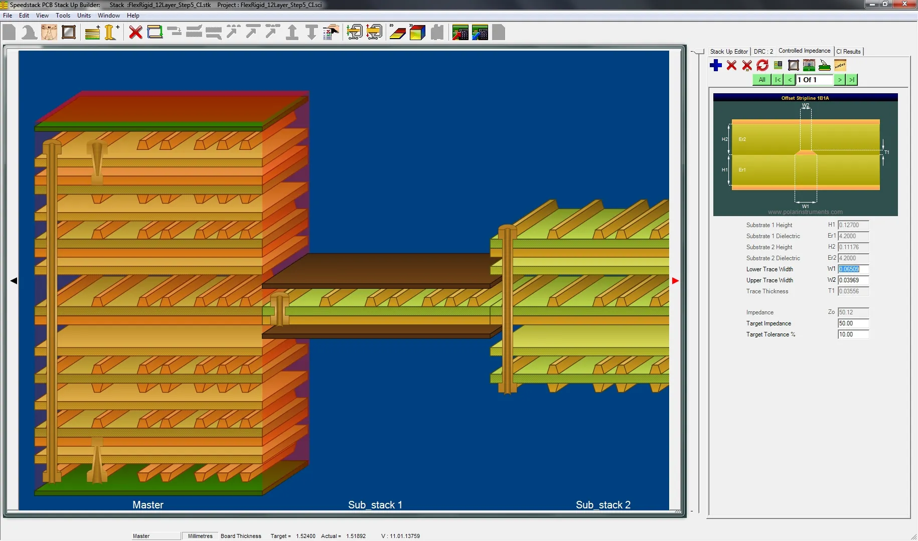
Bend radius refers to the smallest curvature to which the flexible portion of a rigid-flex PCB can be bent without causing material damage or electrical discontinuity. In rigid-flex designs, the flex section typically consists of polyimide substrates, copper conductors, and coverlay materials stacked to form interconnects between rigid boards. The minimum bend radius rigid-flex PCB achieves depends on the total thickness of this flex stack, copper ductility, and application demands. Static bending occurs during assembly or installation with limited cycles, while dynamic bending involves repeated flexing in operation. Neglecting proper bend radius invites excessive strain on inner and outer fibers, accelerating degradation. Factory-driven design emphasizes defining bend zones clearly in stack-up drawings to align with manufacturing capabilities.
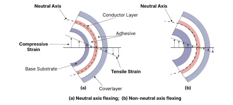
This parameter matters because rigid-flex PCBs operate in space-constrained environments where tight folds are tempting, yet they risk reliability if not managed. Strain distribution across the bend radius determines trace integrity, with outer layers experiencing tensile stress and inner layers compression. Electrical engineers evaluate bend radius alongside via placement and trace routing to prevent stress risers. Standards-aligned approaches ensure compliance with performance expectations across product lifecycles. Insights from production floors show that bend radius violations account for a notable portion of qualification rejections.
Technical Principles of Bend Radius
The mechanics of bending in rigid-flex PCBs involve hoop stress and fiber elongation, governed by the geometry of the flex section. When bent, the neutral axis shifts slightly due to material asymmetry, but strain is approximated as proportional to distance from this axis divided by bend radius. Smaller radii amplify strain, particularly in thicker stacks or rolled annealed copper foils prone to cracking. Rigid-flex PCB bend radius calculation starts with measuring flex section thickness, including copper, dielectric, and coverlay, then applying multipliers from established guidelines. Factors like layer count influence these multipliers, as multi-layer flex demands larger radii to accommodate interlayer stresses. Temperature and humidity during flexing further modulate material properties, underscoring the need for environmental testing.
IPC-2223E outlines rigid-flex PCB bend radius standards, providing ratios relative to flex thickness for static and dynamic conditions based on conductor layers and copper type. These standards differentiate single-sided from multi-layer configurations to guide designers toward safe limits. For instance, static applications allow tighter radii than dynamic ones, where fatigue accumulation dominates. Electrical engineers use these ratios in simulation tools to predict strain levels before prototyping. Factory validation confirms that adhering to such standards minimizes variability in bend performance across batches.
Rigid-Flex PCB Bend Radius Failure Modes
Exceeding the minimum bend radius rigid-flex PCB tolerance triggers failures like copper trace cracking, where tensile strain on the outer bend exceeds ductility limits. Cracks initiate at trace edges or corners, propagating under cyclic loading and causing open circuits. Delamination between coverlay and substrate occurs from shear stresses, especially if adhesives lack sufficient peel strength. In dynamic bending rigid-flex PCB scenarios, fatigue cracking dominates, with microcracks growing over cycles until electrical discontinuity. Vias near bend zones suffer barrel cracking due to differential expansion. Factory inspections often reveal these issues post-flex testing, highlighting the interplay of design and material choices.
Other failures include coverlay wrinkling or tearing, compromising insulation and exposing conductors to environmental hazards. Adhesive flow under heat and bend exacerbates interlayer separation in multi-layer flex. Rigid-flex PCB bend radius failure escalates in high-vibration environments, where resonant frequencies amplify local stresses. Cross-sectional analysis post-failure shows elongated grains in copper as precursors to fracture. Engineers mitigate by oversizing radii and incorporating strain-relief features like teardrops at pads.
Standards and Calculation Methods
Rigid-flex PCB bend radius standards from IPC-2223E provide factory-proven multipliers for thickness, ensuring consistent reliability. Calculation involves total flex height h, then minimum radius r = k * h, where k varies by application: lower for static install bends, higher for repeated flexing. Layer count adjusts k upward for multi-layer due to cumulative strain. Copper foil type—electrodeposited versus rolled annealed—affects tolerance, with RA copper enabling tighter radii. Software aids rigid-flex PCB bend radius calculation by modeling 3D stress, but standards anchor final values. IPC-6013E qualification tests verify bend endurance through cyclic flexing, confirming design margins.
For dynamic bending rigid-flex PCB, standards recommend significantly larger radii to achieve cycle life targets, often 10 times static values. Factory processes incorporate bend radius into DFM reviews, simulating production folds. Electrical engineers iterate stack-ups to balance signal integrity with mechanical limits.
Best Practices for Reliable Design
Select materials with high flex endurance, such as adhesiveless laminates for tight radii, and route traces perpendicular to bend lines to distribute stress evenly. Maintain bend zones free of vias and dense routing, spacing them at least 10 times flex thickness from transitions. Oversize radii by 20 percent for safety margins, especially in dynamic applications. Simulate bending with FEA to visualize strain hotspots before fab. Factory alignment involves specifying bend direction—convex or concave—in artwork notes.
For dynamic bending rigid-flex PCB, limit to single or double-layer flex with RA copper, and incorporate slack loops if space allows. Perform qualification per IPC-6013E, cycling to 10,000 bends minimum while monitoring continuity. Collaborate with manufacturers early for stack-up feasibility. These practices extend service life in harsh environments.
Conclusion
Bend radius profoundly impacts rigid-flex PCB reliability, dictating strain management and failure resistance in flex sections. Adhering to rigid-flex PCB bend radius standards like IPC-2223E ensures designs withstand static installs and dynamic demands. Proper rigid-flex PCB bend radius calculation, informed by thickness and layers, prevents common pitfalls like trace cracks and delamination. Electrical engineers benefit from factory insights emphasizing testing and margins. Prioritizing these elements yields robust, long-lasting assemblies.
FAQs
Q1: What is the rigid-flex PCB bend radius calculation process?
A1: Rigid-flex PCB bend radius calculation begins with measuring flex section thickness, including copper, dielectric, and coverlay. Apply multipliers from IPC-2223E based on layer count and static or dynamic use. For example, static bends use lower ratios than dynamic ones requiring fatigue resistance. Verify with simulations and prototype testing to confirm strain stays below material limits. This factory-aligned method optimizes reliability.
Q2: What determines the minimum bend radius rigid-flex PCB?
A2: The minimum bend radius rigid-flex PCB depends on flex stack thickness, copper type, and application cycles. IPC-2223E standards provide ratios preventing excessive outer fiber strain. Single-layer designs tolerate tighter radii than multi-layer. Factory DFM reviews adjust for manufacturing tolerances. Always factor in environmental conditions for accurate limits.
Q3: How do rigid-flex PCB bend radius standards guide design?
A3: Rigid-flex PCB bend radius standards in IPC-2223E specify safe ratios relative to thickness for static and dynamic bending. They account for layer variations and foil ductility to avoid cracking. IPC-6013E complements with qualification tests. Engineers use these for compliant, reliable layouts. Production insights stress early standard integration.
Q4: What causes rigid-flex PCB bend radius failure in dynamic applications?
A4: Rigid-flex PCB bend radius failure in dynamic bending rigid-flex PCB arises from fatigue cracking under repeated cycles. Too-small radii exceed copper ductility, initiating microcracks. Delamination and coverlay tears follow from shear. Mitigate with larger radii per standards and RA copper. Testing reveals issues early.
References
IPC-2223E — Sectional Design Standard for Flexible/Rigid-Flexible Printed Boards. IPC, 2020
IPC-6013E — Qualification and Performance Specification for Flexible/Rigid-Flexible Printed Boards. IPC, 2021