Introduction
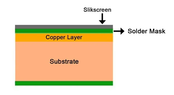
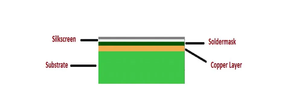
Single-sided printed circuit boards represent the simplest form of PCB construction, featuring conductive traces on only one side of the base material. The substrate serves as the foundational element, providing mechanical support and electrical insulation for the copper layer. In single-sided PCB design, selecting the appropriate substrate directly influences overall performance, cost, and reliability. Engineers must consider factors such as material composition, thickness, and environmental demands to ensure optimal functionality. This article explores the critical role of substrates, focusing on common single-sided PCB substrate materials like FR4 and CEM-1, along with key design considerations.
Substrates in single-sided PCBs differ from those in multilayer boards due to the absence of vias and internal layers, simplifying fabrication but emphasizing the need for robust base properties. Proper substrate choice prevents issues like delamination or warpage during assembly and operation.
Understanding Substrates in Single-Sided PCBs
A substrate in PCB terminology refers to the dielectric core material that supports the conductive copper foil on one side. It must exhibit high insulation resistance, dimensional stability, and compatibility with etching and soldering processes. In single-sided designs, the substrate handles all mechanical stress without additional layers for reinforcement. Common single-sided PCB substrate materials include FR4 and CEM-1, each suited to specific applications based on cost and performance needs.
The relevance of substrates stems from their impact on electrical performance, thermal management, and manufacturability. For instance, the substrate's dielectric constant affects signal propagation, even in low-frequency single-sided circuits. Mechanical properties determine resistance to bending or vibration in end-use environments. As per IPC-4101, base materials are qualified for consistent properties across production.
Choosing the wrong substrate can lead to failures such as trace cracking or poor solder joint integrity. Engineers prioritize materials that align with IPC standards for qualification and performance.
Key Single-Sided PCB Substrate Materials
FR4: The Versatile Standard
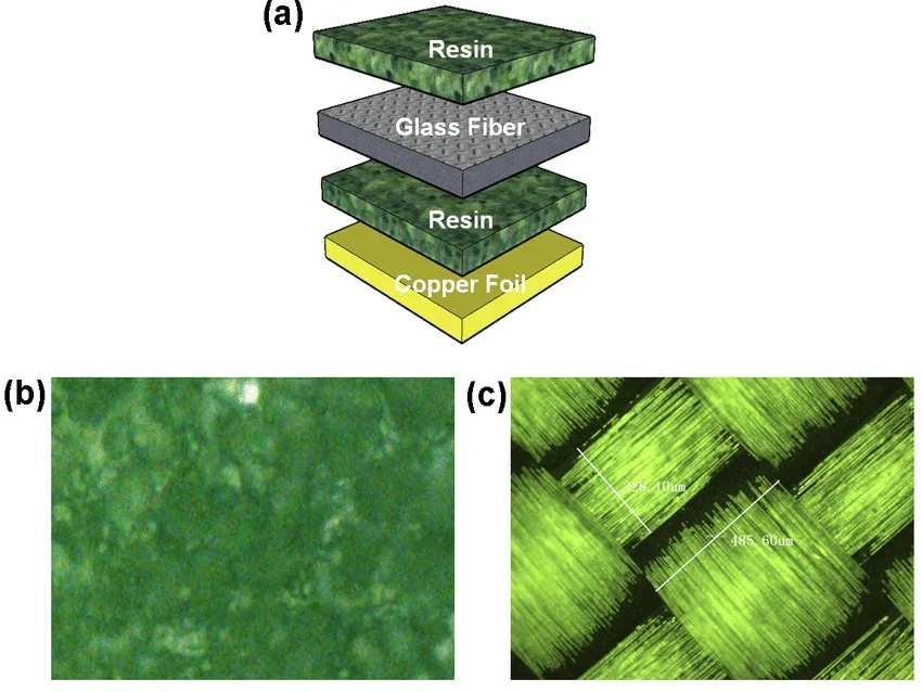
Single-sided PCB FR4 consists of woven glass fabric impregnated with epoxy resin, offering flame retardancy and balanced properties. This material provides excellent mechanical strength, making it suitable for applications requiring durability under mechanical stress. Its low moisture absorption ensures stable electrical performance in humid conditions. FR4 supports standard fabrication processes like drilling and plating, though single-sided boards rarely need extensive via formation.
Compared to other options, single-sided PCB FR4 excels in thermal stability, resisting deformation during soldering. It maintains integrity across a wide temperature range, ideal for consumer electronics and industrial controls. The glass reinforcement minimizes expansion mismatches with copper, reducing warpage risks.
CEM-1: Cost-Effective Choice
Single-sided PCB CEM-1 uses a cellulose paper core with epoxy resin and surface glass fabric layers, prioritizing affordability for high-volume production. This composite delivers adequate insulation for simple circuits without the need for high-speed signals. Its punchability facilitates cost savings in fabrication, especially for non-plated designs. However, CEM-1 exhibits higher moisture sensitivity than FR4, necessitating controlled storage conditions.
CEM-1 suits low-power applications like household appliances where mechanical demands are moderate. It aligns with IPC-4101 specifications for basic rigid boards, ensuring compatibility with standard processes. Engineers select it when budget constraints outweigh premium performance needs.
The Impact of Single-Sided PCB Substrate Thickness
Single-sided PCB substrate thickness profoundly affects board rigidity, warpage susceptibility, and assembly compatibility. Thinner substrates, often around 0.6 mm to 1.0 mm, enhance flexibility for compact designs but increase bending risks during handling. Standard thicknesses from 1.0 mm to 1.6 mm provide optimal balance for most applications, supporting component mounting without excessive flex.
Thicker substrates up to 3.2 mm improve mechanical stability in vibration-prone environments, though they raise material costs and weight. Thickness influences thermal dissipation, as thinner boards cool faster but may warp under heat gradients. Designers must account for copper weight interactions, ensuring uniform lamination per IPC-6012 guidelines.
Improper thickness selection leads to issues like solder mask cracking or poor conformal coating adhesion. Finite element analysis during design helps predict warpage based on thickness and material CTE.
Technical Principles Governing Substrate Performance
Substrates function through their laminate structure, where resin binds reinforcement fibers for dielectric and mechanical properties. In single-sided PCBs, the substrate's coefficient of thermal expansion (CTE) must closely match copper to prevent delamination during reflow. FR4's glass weave achieves lower Z-axis CTE variability compared to CEM-1's paper core, enhancing reliability.
Electrical insulation relies on high dielectric strength, preventing breakdowns under voltage stress. Moisture absorption alters these properties, with FR4 outperforming CEM-1 in high-humidity scenarios. Thermal conductivity, though modest in both, aids heat spreading from traces.
Fabrication involves pressing copper foil onto the substrate under heat and pressure, forming a uniform bond. Post-lamination, etching reveals traces while preserving substrate integrity. Standards like IPC-2221 guide spacing and clearance to leverage substrate capabilities.
Warpage arises from asymmetric stresses, exacerbated in thinner single-sided PCB substrate thicknesses. Controlled curing and symmetric solder mask application mitigate this.
Best Practices for Substrate Selection and Design
Select single-sided PCB substrate materials based on application demands: FR4 for demanding thermal cycles, CEM-1 for cost-sensitive prototypes. Evaluate operating temperature, humidity, and mechanical loads early in design. Verify material qualification against IPC-4101 to ensure consistency.
Optimize single-sided PCB substrate thickness by simulating mechanical loads and thermal profiles. Standard 1.6 mm suits most, but adjust for enclosure fit or component height. Incorporate panelization with fiducials for precise handling.
Design traces to minimize current-induced heating, leveraging substrate's inherent dissipation. Avoid sharp bends near edges to reduce stress concentrations. Test prototypes for warpage using dial gauges post-fabrication.
Specify solder mask and silkscreen uniformly to balance surface tensions. Collaborate with fabricators on material availability to avoid substitutions.
Troubleshooting Common Substrate Issues
Warpage tops concerns in single-sided designs, often from CTE mismatch or uneven cooling. Thinner single-sided PCB substrate thicknesses amplify this; counter with baking before assembly. Delamination signals poor resin-copper adhesion, traceable to contaminated substrates.
Moisture-related failures in CEM-1 manifest as insulation shorts; implement vacuum packaging. Excessive flex in thin boards causes trace fatigue; reinforce with standoffs or thicker variants.
Diagnostic tools like cross-section microscopy reveal laminate voids. Adhere to IPC-A-600 for acceptability criteria during inspection.
Conclusion
Substrates form the backbone of single-sided PCB design, dictating mechanical, electrical, and thermal outcomes. Single-sided PCB substrate materials like FR4 and CEM-1 offer trade-offs in performance versus cost, while thickness fine-tunes rigidity and stability. By aligning choices with application needs and standards such as IPC-4101 and IPC-6012, engineers achieve reliable boards. Thoughtful selection enhances manufacturability and longevity, ensuring single-sided PCBs meet diverse engineering challenges effectively.
FAQs
Q1: What are the most common single-sided PCB substrate materials?
A1: Single-sided PCB substrate materials primarily include FR4 and CEM-1. FR4 provides superior mechanical strength and thermal stability due to its glass epoxy composition, suiting moderate to high-stress applications. CEM-1, with its paper-epoxy core, offers cost savings for simple, low-power circuits. Selection depends on budget, environment, and performance per IPC-4101 specs. Always verify compatibility with assembly processes.
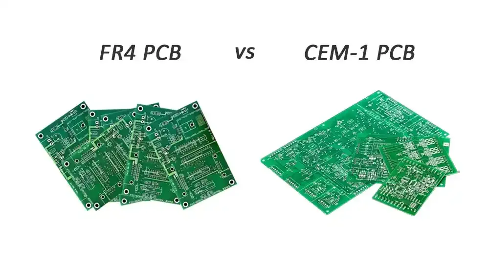
Q2: How does single-sided PCB FR4 compare to CEM-1?
A2: Single-sided PCB FR4 outperforms CEM-1 in mechanical strength, moisture resistance, and thermal performance, making it ideal for durable designs. CEM-1 is cheaper and easier to punch but limits use to non-PTH single-sided boards due to lower rigidity. FR4 handles wider temperature ranges without degradation. Choose based on reliability needs versus cost constraints.
Q3: What is the role of single-sided PCB substrate thickness in design?
A3: Single-sided PCB substrate thickness determines rigidity, warpage risk, and thermal management. Common ranges of 0.6 mm to 1.6 mm balance flexibility and strength; thicker options enhance stability in vibrations. Thinner boards suit compact assemblies but require careful handling. Simulate effects to align with mechanical demands and standards.
Q4: When should engineers choose CEM-1 for single-sided PCBs?
A4: Opt for single-sided PCB CEM-1 in high-volume, low-cost applications like basic controls where premium thermal or mechanical properties are unnecessary. It excels in punchable designs without plated holes. Avoid in humid or high-heat environments due to higher moisture absorption. Confirm specs against IPC guidelines for reliability.
References
IPC-4101B — Specification for Base Materials for Rigid and Multilayer Printed Boards. IPC, 2006
IPC-2221B — Generic Standard on Printed Board Design. IPC, 2003
IPC-6012E — Qualification and Performance Specification for Rigid Printed Boards. IPC, 2015
IPC-A-600K — Acceptability of Printed Boards. IPC, 2020