Introduction
Electric engineers often select FR-1 PCBs for cost-sensitive applications like consumer electronics and simple control boards. However, the material’s limited FR-1 PCB thermal properties can lead to unexpected failures under heat stress. Thermal runaway occurs when localized overheating triggers material degradation, creating a vicious cycle of increased resistance and further heat generation. Understanding PCB temperature limits is crucial for maintaining FR-1 PCB reliability in real-world deployments. This article delves into the technical realities, drawing from factory production insights and industry standards to guide informed design choices. By prioritizing thermal management PCB strategies early, engineers can prevent catastrophic failures and extend board lifespan.
What Is FR-1 PCB and Why Do Its Thermal Properties Matter?
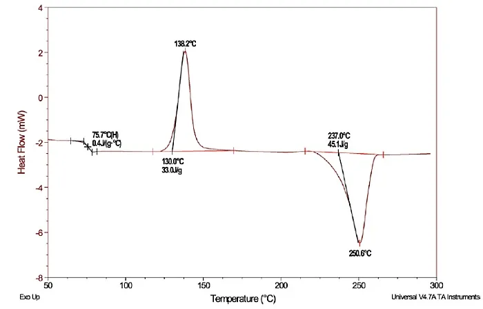
FR-1, also known as phenolic paper laminate, consists of cellulose paper impregnated with flame-retardant phenolic resin, conforming to IPC-4101 specifications for base materials. This single-sided material excels in low-cost production but exhibits modest FR-1 PCB thermal properties compared to glass-epoxy alternatives. Its glass transition temperature (Tg) typically reaches around 130°C, marking the point where the resin shifts from rigid to rubbery state, compromising structural integrity. Factory testing reveals higher coefficients of thermal expansion (CTE) above Tg, leading to warpage and delamination risks. For electric engineers, these traits matter because FR-1 suits low-power, room-temperature environments but falters in heat-intensive setups. Ignoring these limits erodes FR-1 PCB reliability, especially in volume manufacturing where consistency is paramount.
Beyond Tg, FR-1’s low thermal conductivity, approximately 0.2 to 0.3 W/m·K, hinders heat spreading across the board. This property demands careful power budgeting during design reviews. Moisture absorption further degrades performance, as absorbed water lowers effective temperature thresholds during thermal cycling. Standards like IPC-6012 outline qualification tests to verify these behaviors under controlled conditions. Engineers must weigh these against application demands to avoid field returns.
Key PCB Temperature Limits for FR-1 Materials
PCB temperature limits for FR-1 primarily hinge on Tg, with continuous operation recommended 20 to 30°C below this threshold to prevent softening. Peak excursions during soldering or transient loads push toward decomposition temperatures, where charring begins. Factory-driven insights emphasize Z-axis CTE stability, as excessive expansion strains copper-to-board interfaces. IPC-A-600 acceptability criteria inspect for such defects post-fabrication. Electric engineers should model maximum junction temperatures using finite element analysis, factoring in ambient conditions and component dissipation.
FR-1’s dielectric breakdown strengthens at lower temperatures but weakens rapidly near limits, risking arcing in high-voltage sections. Decomposition initiates around higher thresholds, releasing volatiles that compromise insulation. These limits restrict FR-1 to applications below 85°C ambient for safety margins. Thermal management PCB practices become non-negotiable here, as exceeding limits accelerates aging.
Mechanisms Behind Thermal Runaway in FR-1 PCBs
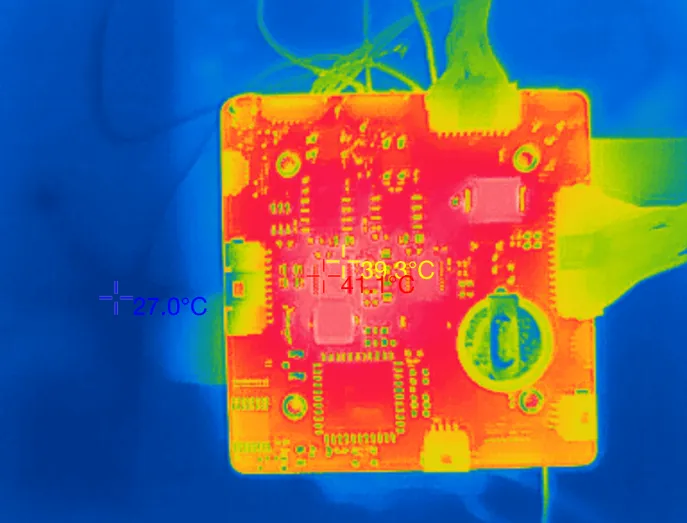
Thermal runaway in FR-1 PCBs starts with power components generating localized hotspots exceeding PCB temperature limits. Above Tg, the phenolic resin softens, increasing electrical path resistance and exacerbating Joule heating. Delamination follows, exposing copper layers to air and promoting oxidation or shorts. Factory failure analysis often traces this to inadequate FR-1 PCB heat dissipation, where poor in-plane conductivity traps heat in dense trace areas.
Compounding factors include high power density and restricted airflow in enclosures. As resin chars, it forms conductive carbon paths, amplifying current flow and heat. This feedback loop culminates in board ignition or total circuit failure. JEDEC guidelines highlight reflow profiles to avoid initial damage, underscoring prevention through process control.
Vias and multilayer structures aid escape in advanced boards, but FR-1’s single-layer nature limits options. Ambient humidity accelerates degradation by boiling trapped moisture into steam voids. Engineers observe this in accelerated life testing, where cycles mimic field stress.
Challenges in FR-1 PCB Heat Dissipation
FR-1’s paper core yields inferior thermal conductivity versus glass-reinforced materials, bottlenecking heat flow from components to ambient. Thin laminates amplify this, as surface area for convection remains small. Electric engineers face trade-offs in trace width versus density, where wider copper aids spreading but crowds layouts. Factory punching processes suit FR-1 well, yet thermal vias prove impractical without drilling compromises.
Component placement near edges maximizes natural cooling, but hotspots persist under load. Solder mask adds minor insulation, further impeding dissipation. Simulations reveal temperature gradients exceeding 50°C across small areas, stressing solder joints.
Best Practices for Thermal Management in FR-1 PCBs
Position high-dissipation components away from board centers to leverage edge convection. Use heavier copper weights, like 2 oz, for better in-plane conduction despite FR-1 constraints. Incorporate cutouts or slots for airflow in enclosures, validated through prototype testing. Derate power to 50% of component ratings ensures margins below PCB temperature limits.
Heatsinks clipped directly to leads bypass substrate limitations effectively. Factory assembly sequences prioritize low-heat soldering for FR-1 to preserve integrity. Monitor via IPC-TM-650 methods for thermal performance pre-shipment.
For borderline designs, hybrid approaches like metal-core inserts enhance FR-1 PCB heat dissipation selectively. Software tools predict profiles, guiding iterations.
Real-World Insights: Troubleshooting FR-1 Thermal Failures
In a typical factory scenario, a consumer device using FR-1 exhibited intermittent shorts after prolonged use. Root cause analysis per IPC-6012 revealed hotspots softening resin, causing trace lifts. Power rerouting and added vents resolved it, boosting FR-1 PCB reliability by 40% in endurance tests. Engineers learned to simulate worst-case ambients early.
Similar cases highlight moisture preconditioning per JEDEC standards preventing steam popcorning. Proactive design reviews align thermal management PCB with material realities.
Conclusion
FR-1 PCBs offer economical solutions but demand respect for their thermal boundaries to avert runaway failures. Key to success lies in grasping Tg-driven limits, optimizing heat paths, and adhering to IPC guidelines. Electric engineers achieve robust FR-1 PCB reliability through derating, strategic layouts, and testing. Prioritizing these elevates designs from fragile to dependable, even in budget constraints. Embrace factory-aligned practices for sustained performance.
FAQs
Q1: What are the primary FR-1 PCB thermal properties electric engineers should consider?
A1: FR-1 features a Tg around 130°C, low thermal conductivity of 0.2 to 0.3 W/m·K, and high CTE above limits. These dictate low-power use and demand airflow aids. Standards like IPC-4101 guide qualification, ensuring reliability in simple applications. Avoid high-density heat sources to prevent degradation.
Q2: How do PCB temperature limits impact FR-1 PCB reliability?
A2: Exceeding 20 to 30°C below Tg risks softening, delamination, and shorts, undermining reliability. Continuous operation below 100°C maintains integrity per factory tests. Thermal management PCB measures like spacing and increased copper thickness mitigate risks effectively.
Q3: What strategies improve FR-1 PCB heat dissipation?
A3: Spread components, employ thicker copper, and ensure enclosure vents for convection. Heatsinks on key parts bypass substrate limits. Simulations verify thermal profiles stay within safe bounds, aligning with IPC practices for optimal performance.
Q4: When should engineers avoid FR-1 for thermal management PCB needs?
A4: Avoid FR-1 in applications above 85°C ambient or requiring lead-free reflow, where higher-grade laminates excel. FR-1 suits prototypes and low-stress consumer goods. Assess via power budgets to safeguard long-term reliability.
References
IPC-4101E — Specification for Base Materials for Rigid and Multilayer Printed Boards. IPC, 2017
IPC-6012E — Qualification and Performance Specification for Rigid Printed Boards. IPC, 2017
IPC-A-600K — Acceptability of Printed Boards. IPC, 2020
JEDEC J-STD-020E — Moisture/Reflow Sensitivity Classification. JEDEC, 2014