What Are Cold Solder Joints and Why Are They a Problem?
A cold solder joint represents a common, yet critical, defect encountered in PCB assembly. It occurs when solder fails to properly melt and form a strong metallurgical bond with a component lead or a pad on the circuit board. The outcome is a connection that is either weak, incomplete, or entirely unreliable, often leading to intermittent electrical signals, erratic device performance, or even total circuit failure. These issues can be particularly challenging as they may not be immediately apparent and often surface only after a period of operation.
Typically, cold solder joints result from insufficient heat during the soldering process, inadvertent movement of components before the solder solidifies, or inadequate preparation of the surfaces to be joined. For instance, if a soldering iron’s temperature is below the melting point of the solder (e.g., below 183°C for standard lead-free solder), the joint might appear superficially connected but lacks the crucial intermetallic bond necessary for robust electrical continuity. This deficiency can lead to a significant increase in electrical resistance, sometimes exceeding 10 ohms in severe cases, which can critically disrupt signal integrity, especially in high-frequency applications above 100 MHz. A thorough understanding of cold solder joints and effective repair methods is thus paramount for maintaining the long-term reliability of any PCB.
Cold Solder Joint Diagnosis: Identifying the Issue
Early diagnosis of cold solder joints is essential to prevent more extensive and costly rework or catastrophic board failures. Employing effective solder joint inspection techniques can help pinpoint these elusive defects.
Visual Inspection Cues
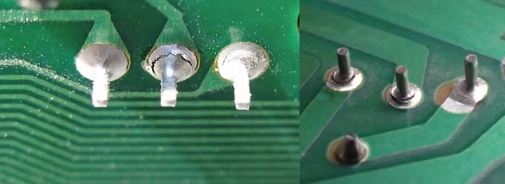
● Appearance: A healthy solder joint should exhibit a smooth, shiny, and concave fillet shape, indicating proper wetting and flow. In contrast, cold solder joints often appear dull, grainy, rough, or even cracked. They may also show uneven solder distribution or a “balled up” appearance rather than a clean, feathered edge.
● Magnification: For smaller components and finer details, using a magnifying glass or a digital microscope is highly recommended. These tools reveal subtle imperfections that might be missed with the naked eye.
H3: Physical and Electrical Verification
● Gentle Movement Test: Carefully and gently try to wiggle the component in question. If it feels loose or moves with minimal force, it’s a strong indicator that the solder joint has not properly bonded. Exercise caution to avoid exerting excessive force, which could inadvertently damage the component or the PCB trace.
● Multimeter Resistance Test: Utilize a multimeter to measure continuity and resistance across the suspected joint. A healthy joint should show very low resistance, ideally below 0.1 ohms. Resistance values exceeding 1 ohm strongly suggest a poor or cold solder connection. For sensitive circuits, even minor increases in resistance can impact performance, especially in high-current power delivery systems.
● Thermal Imaging (Advanced): In more sophisticated setups, a thermal camera can be employed to detect cold solder joints. During operation, a poorly bonded joint often presents as an abnormal hot spot due to increased electrical resistance, providing a visual cue for diagnosis.
By systematically applying these diagnostic methods, you can effectively identify cold solder joints before they escalate into major functional problems. Once detected, the next crucial step in PCB soldering troubleshooting is to perform an effective repair using the appropriate tools and techniques.
Why Choose Hot Air Rework for Solder Joint Repair?
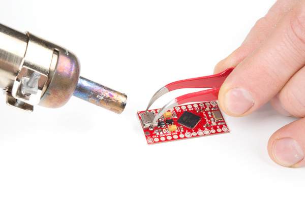
Hot air rework is recognized as one of the most efficient and versatile solder joint repair methods, particularly well-suited for surface-mount devices (SMDs) and densely populated PCBs. Its advantages over traditional soldering irons are significant. Unlike an iron, which concentrates heat on a single point, a hot air station delivers a controlled, wide stream of heated air. This allows for the simultaneous reflow of solder across an entire component or multiple adjacent joints, ensuring uniform heat distribution. This even heating characteristic is vital in preventing localized thermal stress and potential damage to nearby sensitive components or the PCB substrate itself.
Hot air rework effectively simulates the conditions of a reflow oven used in pcb mass production, making it ideal for repairing cold joints. By elevating the solder to its precise melting point (typically 217-230°C for lead-free solder), it encourages the solder to properly wet, flow, and form a robust intermetallic bond with both the component lead and the PCB pad. This method is exceptionally valuable for modern PCBs that feature fine-pitch components, where precision and controlled heat application are paramount. Furthermore, hot air rework stations offer adjustable temperature and airflow settings, providing operators with precise control over the process. For example, a typical setup for lead-free solder reflow might involve a temperature of 300-350°C coupled with a moderate airflow to prevent accidental displacement of small components. This inherent flexibility makes hot air rework an indispensable tool for comprehensive PCB soldering troubleshooting.
Step-by-Step Guide to Hot Air Rework Solder Reflow
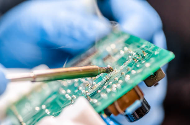
To effectively fix cold solder joints using hot air rework, follow this detailed procedure to ensure reliable and lasting results. Prior to starting, ensure you have a hot air rework station, appropriate flux, and all necessary personal safety gear.
1. Prepare the Workspace: Set up your workstation in a well-ventilated area. Use a heat-resistant mat to protect your work surface. Secure the PCB firmly in a specialized holder or vise to prevent any movement during the rework process, ensuring stability.
2. Apply Flux: Dispense a small, precise amount of flux directly onto the cold solder joint(s). Flux serves multiple critical functions: it cleans the metal surfaces by removing oxidation, facilitates proper solder wetting, and helps the solder flow smoothly and evenly. A “no-clean” flux is often preferred as it leaves minimal residue, eliminating the need for subsequent cleaning.
3. Configure the Hot Air Station: Adjust the temperature and airflow settings on your hot air rework station according to the specific type of solder being used. For lead-free solder, set the temperature typically between 300-350°C. For airflow, opt for a low to medium setting (approximately 20-30 liters per minute) to ensure even heating without the risk of blowing small components off the board.
4. Heat the Joint: Position the hot air nozzle approximately 1-2 inches (2.5-5 cm) directly above the target joint. Move the nozzle in a gentle, continuous circular motion to ensure even heat distribution across the entire joint area. Continue heating for about 10-20 seconds, observing the solder. You should see the solder visibly melt, become liquid, and flow smoothly, acquiring a bright, shiny appearance as it reflows.
5. Allow for Natural Cooling: Once the solder has reflowed and appears shiny and smooth, carefully remove the hot air nozzle. Allow the joint to cool down naturally, without any forced air or movement of the board. Rapid cooling can induce thermal stress, potentially leading to new cracks or defects in the solder joint.
6. Inspect the Repair: After the joint has completely cooled, perform a thorough visual inspection. Look for a smooth, shiny, and well-formed concave fillet. Additionally, use a multimeter to perform an electrical test, verifying that the joint now exhibits very low resistance, ideally below 0.1 ohms, confirming a strong electrical connection.
Mastering hot air rework solder reflow is a skill that improves significantly with practice. Do not be discouraged if your initial attempts are not flawless; persistence and attention to detail will lead to consistent, high-quality repairs.
Suggested Reading: PCB Soldering Processes and Common Defects Explained
Common Challenges in Hot Air Rework and Their Solutions
While hot air rework is a highly effective technique, it can present specific challenges, particularly for those new to the method. Understanding these common issues in PCB soldering troubleshooting and knowing how to address them will lead to more consistent success.
Overheating Components
Excessive heat applied for too long can irreparably damage sensitive components such as microcontrollers, capacitors, or delicate integrated circuits.
● Solution: To mitigate this, use specialized heat shields or Kapton tape to protect adjacent sensitive parts. Crucially, limit the direct heating time on any single joint to under 30 seconds to prevent thermal damage.
Solder Not Melting
If the solder fails to reflow as expected, it indicates an issue with heat application. This could be due to insufficient temperature settings or excessive airflow that disperses the heat too rapidly.
● Solution: Try increasing the hot air temperature by 20-30°C. Alternatively, reduce the airflow slightly to concentrate the heat more effectively. Regularly ensure your hot air station is accurately calibrated to guarantee precise temperature output.
Component Displacement
High airflow settings can inadvertently blow small surface-mount components off their pads, especially tiny integrated circuits or passive components.
● Solution: Utilize a lower airflow setting, particularly for very small SMDs (e.g., below 20 liters per minute). For extremely miniature or lightweight components, carefully hold them in place with precision tweezers during the initial heating phase until the solder starts to reflow and secure the component.
Uneven Reflow
If the solder melts and flows inconsistently, resulting in an uneven or poorly formed joint, the heat application might be uneven.
● Solution: Ensure you are moving the hot air nozzle in a consistent, controlled circular pattern around the joint to distribute heat uniformly. Applying a fresh, small amount of flux can also significantly improve solder wetting and help it spread evenly across the pads.
By anticipating these potential difficulties and adjusting your technique proactively, you can achieve reliable and high-quality results with your hot air rework solder reflow processes.
Preventing Cold Solder Joints in Future Projects
While hot air rework is an excellent method for repairing existing cold solder joints, the most effective strategy is to prevent their formation during the initial soldering process. Implementing these best practices can significantly reduce defects in your PCB assembly.
● Ensure Proper Heat Application: Always verify that your soldering iron or reflow oven reaches and maintains the correct temperature for the specific solder alloy you are using. For manual soldering with lead-free solder, aim for an iron tip temperature between 260-300°C to ensure full and proper melting and wetting.
● Maintain Clean Surfaces: Before soldering, meticulously clean both the PCB pads and the component leads using isopropyl alcohol. This step removes any dirt, grease, or oxidation layers that can hinder proper solder adhesion and wetting, which are crucial for strong connections.
● Prevent Component Movement: It is critical to keep the component and the PCB absolutely steady and immobile until the solder has completely cooled and solidified. Even the slightest movement during this cooling phase can disrupt the formation of the intermetallic bond, leading directly to a cold solder joint.
● Judicious Flux Application: Flux plays a vital role in preventing oxidation during heating and promoting optimal solder flow. Apply flux generously not only during initial soldering but also during any rework processes to ensure clean, reliable joints.
● Regular Inspection Routine: Incorporate comprehensive solder joint inspection techniques as a routine part of your workflow. Catching potential issues early on allows for immediate rectification, preventing them from developing into more severe, long-term problems or failures.
By consistently integrating these preventive practices into your PCB assembly process, you can dramatically reduce the incidence of cold solder joints, thereby saving significant time and effort on future repairs and ensuring higher product reliability.
Advanced Solder Joint Repair Methods for Complex Issues
For situations involving particularly challenging cold solder joints, such as those on thick multilayer boards or in high-density component areas, more advanced repair methods may be required. These techniques offer enhanced control and precision.
Preheating the PCB
For thicker PCBs, especially those with multiple layers, preheating the entire board before applying localized hot air rework is highly beneficial.
● Method: Use a dedicated preheat plate or a specialized oven to uniformly warm the entire PCB to a temperature typically between 100-120°C.
● Benefit: This preheating step significantly reduces the thermal shock and stress that localized hot air can impose on the board, thereby minimizing the risk of warping, delamination, or damage to other components. Once preheated, hot air can be applied to the specific joint for reflow.
Adding Fresh Solder
If an existing cold joint has insufficient solder volume, or if the solder appears degraded or contaminated, introducing fresh solder can be a superior approach.
● Method: First, use a desoldering braid or a desoldering pump to carefully remove the old, compromised solder from the joint. Then, apply a small amount of fresh solder.
● Benefit: Afterwards, use the hot air station to reflow this new solder. Ensure the fresh solder alloy matches the original solder used on the board (e.g., SAC305 for lead-free boards) to ensure metallurgical compatibility and a strong, consistent bond. This technique effectively rebuilds the joint from scratch, often resulting in a more robust connection.
These advanced methods require a higher degree of precision, specialized equipment, and greater experience, but they provide robust solutions for even the most challenging cold solder joint issues encountered on complex circuit boards.
Essential Tools for Effective PCB Soldering Troubleshooting
Equipping yourself with the right tools is paramount for accurate cold solder joint diagnosis and efficient repair. Investing in quality equipment will streamline your workflow and enhance the reliability of your repairs.
● Hot Air Rework Station: This is the cornerstone tool for reflowing cold solder joints. Choose a model with precise, adjustable temperature controls (typically up to 400°C) and variable airflow settings. Look for stations that offer a range of interchangeable nozzles to accommodate different component sizes and types.
● Multimeter: A reliable digital multimeter is indispensable for performing electrical tests. It's crucial for checking continuity, measuring resistance, and identifying short circuits. Opt for a meter with high accuracy (ideally within 0.01 ohms) to detect even subtle changes in joint resistance.
● Flux and Solder Supplies: Always maintain a consistent supply of high-quality flux, preferably a "no-clean" type to minimize post-rework cleaning. Additionally, ensure you have matching solder wire or solder paste that corresponds to your board's specifications (e.g., lead-free or leaded alloy).
● Magnification Tools: For detailed solder joint inspection, especially on densely populated boards with tiny SMD components, a good magnifying glass, a jeweler’s loupe, or a digital microscope is essential. These tools allow you to clearly observe the fine details of solder fillets and detect microscopic defects.
● Precision Tweezers and Brushes: A set of fine-tip precision tweezers is invaluable for delicately handling small components and for securing them during hot air rework. Soft, anti-static brushes are useful for applying flux and for gently cleaning flux residue after the repair is complete.
Investing in these quality tools not only ensures accurate diagnosis but also facilitates efficient and effective repairs, contributing significantly to a smoother and more successful electronics repair workflow.
Conclusion: Master Cold Solder Joint Repairs with Hot Air Rework
Cold solder joints pose a significant threat to the performance and reliability of any PCB, yet with the application of appropriate techniques, they are entirely rectifiable. By mastering the nuances of cold solder joint diagnosis, skillfully utilizing hot air rework for solder reflow, and implementing rigorous solder joint inspection techniques, you can confidently approach and resolve various PCB soldering troubleshooting challenges. Whether your task involves repairing a single faulty joint or maintaining the integrity of a complex, densely populated board, the solder joint repair methods detailed in this guide provide an invaluable foundation for achieving successful outcomes.
Here at AIVON, we are dedicated to supporting both professional engineers and enthusiastic hobbyists by offering comprehensive resources and innovative solutions for every phase of PCB design and assembly. We encourage you to apply these tips to your projects to ensure that all your circuit boards are constructed with robust and dependable connections. With consistent practice and the right selection of tools, hot air rework will undoubtedly become your preferred and most effective method for rescuing boards afflicted by cold solder joint issues.