Introduction
For electronic hobbyists venturing into the world of radio frequency (RF) circuits, understanding the properties of printed circuit board (PCB) materials is essential. One key property that significantly impacts RF performance is the dielectric constant, often referred to as the Dk value or relative permittivity. This parameter influences how signals propagate through a PCB and plays a critical role in high-frequency applications. Whether you are designing an antenna, a wireless module, or a high-speed digital circuit, grasping the concept of RF PCB dielectric constant can help you make informed material choices. In this guide, we will explore what the dielectric constant means, its frequency and temperature dependence, and why it matters for your projects. Let us dive into the fundamentals to build a solid foundation.
What Is the Dielectric Constant and Why It Matters
The dielectric constant, also known as relative permittivity, measures a material's ability to store electrical energy in an electric field compared to a vacuum. In the context of RF laminate PCBs, it describes how the insulating layer between conductive traces affects signal transmission. A lower Dk value means signals travel faster through the material, which is crucial for high-frequency designs. Conversely, a higher Dk value slows down signals, impacting timing and performance.
Why does this matter for hobbyists? When working on RF projects, such as Wi-Fi modules or amateur radio equipment, signal integrity is vital. The dielectric constant directly influences impedance, phase velocity, and potential signal loss. Choosing a material with an appropriate Dk value ensures your circuit performs as intended, avoiding issues like signal distortion or mismatch. Understanding relative permittivity helps you select the right PCB substrate for your frequency range and application needs.
Technical Principles of Dielectric Constant in RF PCBs
Defining the Dk Value and Relative Permittivity
The Dk value is a dimensionless number representing the ratio of a material's permittivity to that of free space. For RF PCBs, common dielectric materials have Dk values ranging from about 2 to 10, depending on their composition. Materials with low Dk values are often used in high-frequency applications to minimize signal delay and loss. Relative permittivity is simply another term for the dielectric constant, emphasizing its comparison to a vacuum.
Dielectric Constant Frequency Dependence
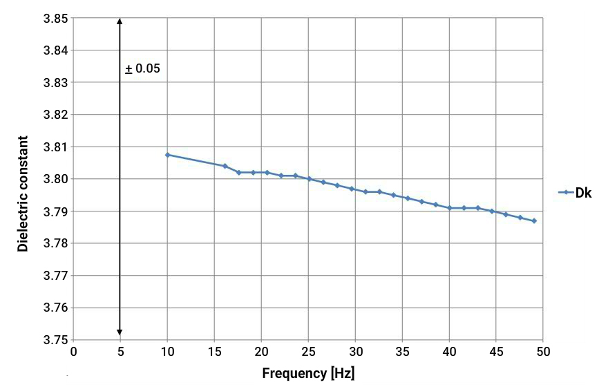
One critical aspect hobbyists must understand is dielectric constant frequency dependence. As frequency increases, the Dk value of a material can change due to the way molecules within the dielectric respond to rapidly alternating electric fields. At higher frequencies, polarization effects diminish, often causing a slight decrease in the dielectric constant. This behavior is especially relevant for RF designs operating in the gigahertz range, where even small variations can affect performance. Always consult material datasheets for frequency-specific Dk values to ensure accurate design calculations.
Dielectric Constant Temperature Dependence
Another important factor is dielectric constant temperature dependence. Temperature fluctuations can alter the molecular structure of a dielectric material, impacting its ability to store charge. In many cases, as temperature rises, the Dk value may increase or decrease slightly, depending on the material's properties. For hobbyists working on outdoor RF projects or devices exposed to varying conditions, selecting a material with stable thermal behavior is crucial. Testing your design under expected temperature ranges can help identify potential issues before deployment.
Impact on Signal Propagation and Impedance
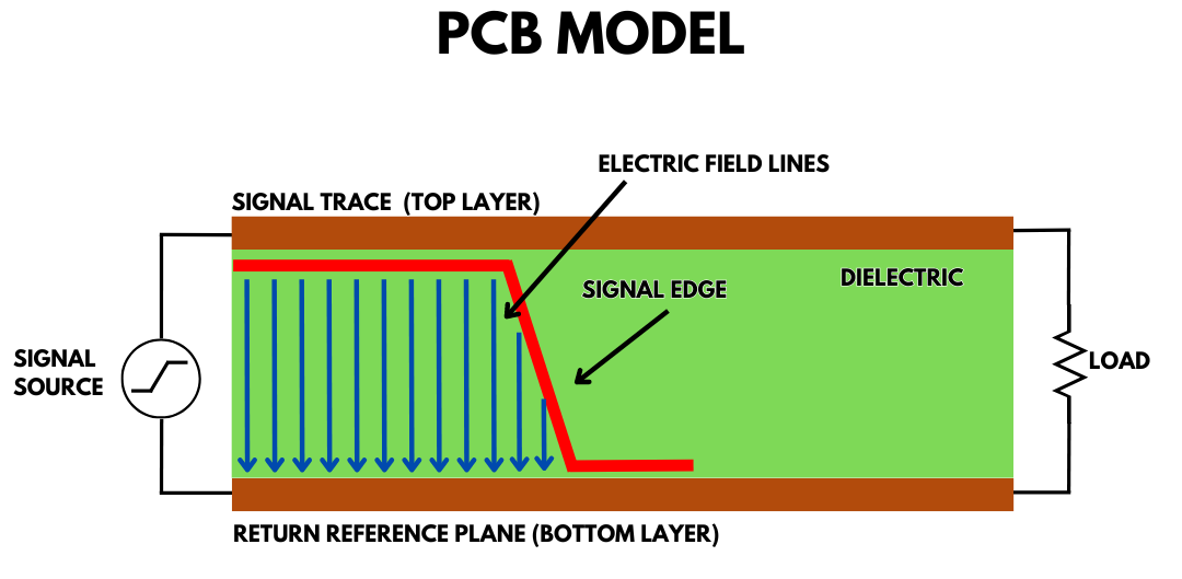
The dielectric constant affects how electromagnetic waves propagate through a PCB. A higher Dk value slows down the signal, reducing the wavelength for a given frequency. This property directly influences the characteristic impedance of transmission lines, a critical parameter in RF design. Mismatched impedance due to an incorrect Dk value can lead to reflections and signal loss. For consistent performance, ensure your PCB material's relative permittivity aligns with your design requirements.
Practical Tips for Selecting RF PCB Materials
Consider Your Frequency Range
When choosing a PCB material, first determine the frequency range of your project. For low-frequency applications, standard materials with moderate Dk values may suffice. However, for RF designs operating above a few hundred megahertz, opt for low-Dk materials to maintain signal speed and minimize loss. Check material specifications for dielectric constant frequency dependence to ensure compatibility with your operating conditions.
Evaluate Thermal Stability
Hobbyists often overlook dielectric constant temperature dependence when selecting materials. If your project will operate in varying temperatures, prioritize materials known for thermal stability. Look for substrates with minimal Dk variation across your expected temperature range. This approach helps maintain consistent performance, especially for portable or outdoor RF devices.
Balance Cost and Performance
High-performance RF materials with low Dk values and stable properties often come at a higher cost. As a hobbyist, weigh the benefits of premium materials against your budget. For prototyping or learning purposes, standard materials may be adequate. However, for critical projects, investing in a suitable substrate can prevent costly redesigns due to signal issues.
Use Design Tools for Simulations
Leverage free or accessible design software to simulate your RF circuit's behavior with different Dk values. These tools allow you to model how relative permittivity affects impedance and signal propagation. Simulations can save time by identifying potential mismatches before you fabricate your PCB, ensuring better results on the first attempt.
Common Challenges and Troubleshooting Tips
Signal Integrity Issues
A frequent challenge in RF PCB design is maintaining signal integrity. If your signals exhibit distortion or unexpected delays, the dielectric constant of your material might be unsuitable. Verify the Dk value at your operating frequency and consider switching to a material with more favorable properties. Double-check your trace dimensions as well, since they interact with the dielectric to determine impedance.
Thermal Performance Problems
If your RF device shows inconsistent behavior under temperature changes, dielectric constant temperature dependence could be the culprit. Test your PCB across a range of temperatures to observe any shifts in performance. If variations are significant, explore alternative materials with better thermal stability to mitigate these effects.
Impedance Mismatch
Impedance mismatch often arises from incorrect assumptions about the dielectric constant. Ensure that your design accounts for the specific Dk value of your chosen material at the target frequency. Use controlled impedance traces and validate your design with simulations or measurements to avoid reflections and signal loss.
Conclusion
Understanding the dielectric constant of RF laminate PCBs is a fundamental skill for electronic hobbyists exploring high-frequency designs. The Dk value, or relative permittivity, governs signal speed, impedance, and overall circuit performance. Factors like dielectric constant frequency dependence and dielectric constant temperature dependence further complicate material selection, requiring careful consideration of operating conditions. By grasping these concepts and applying practical tips, you can choose the right PCB substrate for your projects, ensuring reliable and efficient RF performance. Keep learning and experimenting to refine your skills in this fascinating area of electronics.
FAQs
Q1: What is the RF PCB dielectric constant, and why is it important?
A1: The RF PCB dielectric constant, or Dk value, measures a material's ability to store electrical energy compared to a vacuum. It is crucial because it affects signal speed and impedance in high-frequency circuits. A suitable Dk ensures proper signal propagation, preventing issues like distortion or loss in RF designs such as antennas or wireless modules.
Q2: How does dielectric constant frequency dependence impact my RF project?
A2: Dielectric constant frequency dependence means the Dk value can change with frequency. At higher frequencies, the value often decreases, altering signal behavior. For RF projects in the gigahertz range, this can affect timing and impedance. Always check material data for frequency-specific Dk values to match your design needs.
Q3: Why should I consider dielectric constant temperature dependence in PCB design?
A3: Dielectric constant temperature dependence refers to how the Dk value varies with temperature. Fluctuations can impact signal performance in devices exposed to heat or cold. For outdoor or portable RF projects, choosing a material with stable thermal properties prevents inconsistent behavior and maintains circuit reliability.
Q4: How do I select a material with the right Dk value for my RF PCB?
A4: Selecting a material with the right Dk value involves matching it to your frequency range and application. Low Dk materials suit high-frequency designs for faster signals. Consider thermal stability and use design tools to simulate performance. Balance cost and needs to ensure your RF PCB performs as expected.
References
IPC-6012E — Qualification and Performance Specification for Rigid Printed Boards. IPC, 2020.
IPC-A-600K — Acceptability of Printed Boards. IPC, 2020.
IEC 61189-2 — Test Methods for Electrical Materials, Printed Boards and Other Interconnection Structures and Assemblies. IEC, 2006.